
Diode Cmos Stabilizer

The described circuit employs a diode network designed to maintain a stable voltage level for CMOS (Complementary Metal-Oxide-Semiconductor) circuitry, which is sensitive to variations in supply voltage. The network consists of three diodes: D1 and D2, which work together to achieve a combined forward voltage drop of approximately 1.5 V, and D3, an LED that introduces a forward voltage drop of around 1.7 V.
In operation, as the battery voltage decreases, the output voltage from the diode network is regulated to ensure that the CMOS circuitry receives a consistent voltage supply. This is particularly important in battery-powered applications where voltage levels can fluctuate as the battery discharges. The forward voltage drop of the diodes is critical in determining the effective output voltage. The combined forward voltage of D1 and D2 can be selected based on the specific requirements of the CMOS device, while D3 serves both as a voltage reference and an indicator of the circuit's operational status.
The output voltage can be monitored through a table correlating the battery voltage with the output voltage, illustrating how the diode network compensates for the declining battery voltage. This stabilization mechanism is essential for preserving the integrity and performance of the CMOS circuitry, ensuring reliable operation even as the power source wanes.
In summary, this simple diode network effectively stabilizes the voltage supplied to CMOS devices, utilizing a combination of diodes with specific forward voltage drops to maintain consistent performance in battery-operated systems. The simple diode network can stabilize the voltage supplied to CMOS circuitry from a battery. D1 and D2 must have a c ombined forward-voltage drop of about 1.5 V. And D3 is an LED with a forward-voltage drop of about 1.7 V. The table shows the network"s output voltage as the battery"s voltage declines.
Related Circuits
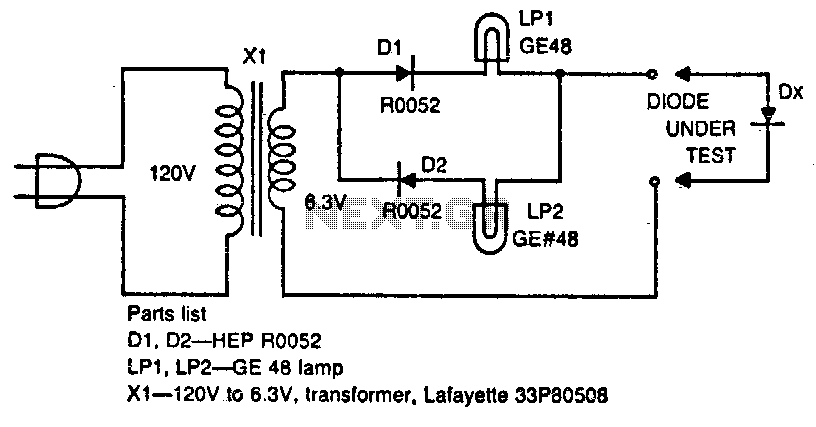
The circuit tests whether a diode is open, shorted, or functioning correctly. If lamp A lights, the diode under test is functional. When lamp B is lit, the diode is good but connected backwards. When both lamps are lit,...
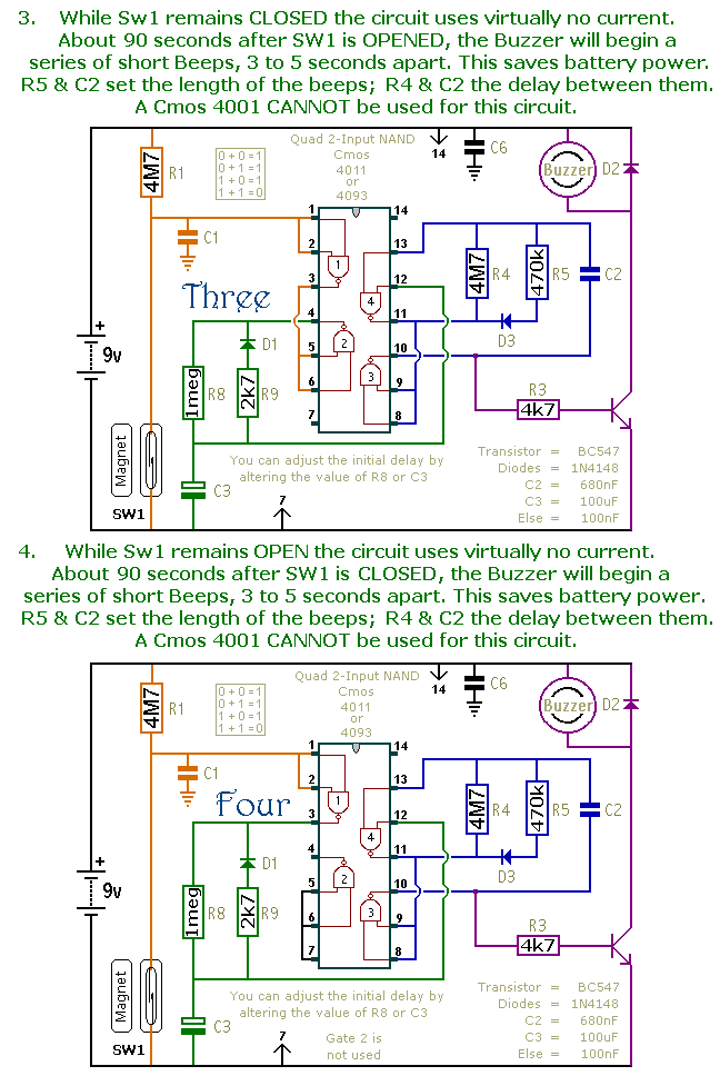
This document presents a collection of compact, self-contained alarm circuits. These circuits are designed to operate with a very low standby current, making them ideal for battery-powered applications. They can be triggered by both normally-open and normally-closed switches, while...
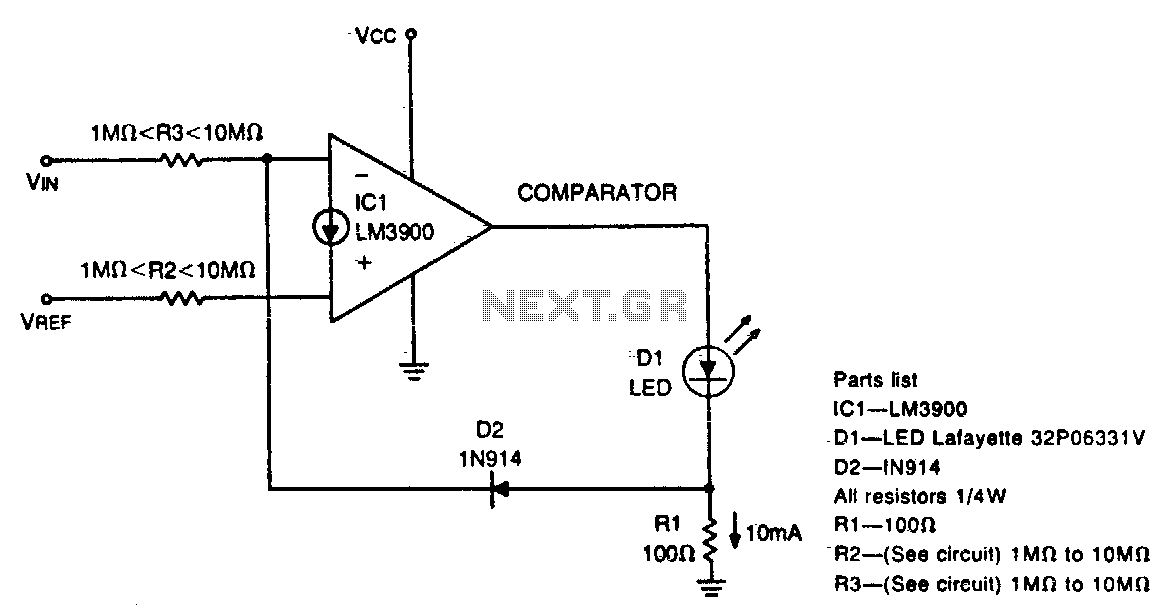
This circuit can drive an LED display with constant current, independent of significant changes in power supply voltage. It can operate with a power supply range of at least 4V to 30V. With 10M resistances for R2 and R3...
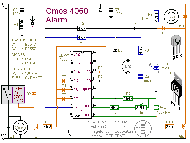
This is a single-zone alarm system equipped with automatic exit, entry, and siren cut-off timers. It is designed to accommodate various types of normally-closed input devices, including magnetic reed contacts, foil tape, and passive infrared sensors (PIRs). Additionally, it...

Frequency-to-voltage converters are integral components in various instrumentation circuits and are also utilized in radio applications as FM demodulators. A notable configuration for these applications is the Diode Charge Pump circuit (DCP), which additionally serves as an AM detector....
It is well understood that utilizing single-supply operational amplifiers (op amps) can present challenges when implementing simple functions in a bipolar signal environment. Often, this necessitates the use of additional op amps and other electronic components. Considering this, it...