
Diode tester

This circuit functions as a diode tester by utilizing two indicator lamps, referred to as lamp A and lamp B. The primary objective is to determine the operational status of a diode under test.
In normal operation, when the diode is functioning correctly and is connected in the correct orientation, lamp A will illuminate, indicating that the diode allows current to pass through it. This condition confirms that the diode is operational and correctly oriented.
If the diode is connected in reverse polarity, lamp B will light up. This indicates that the diode is indeed functional but is not oriented correctly for the intended current flow.
In the scenario where both lamp A and lamp B are illuminated simultaneously, this indicates a short circuit condition within the diode. A shorted diode presents a low-resistance path, allowing current to flow freely in both directions, which causes both lamps to light up.
Conversely, if neither lamp A nor lamp B is lit, this signifies that the diode is open. An open diode does not allow any current to pass through, which is why neither lamp is activated in this state.
The circuit design typically incorporates resistors to limit current to the lamps, ensuring they are not damaged during testing. Additionally, a power source is required to provide the necessary voltage for the test. The arrangement of the components is crucial for accurate testing, and the circuit must be designed to handle the expected voltage and current ratings associated with the diodes being tested.
Overall, this diode testing circuit serves as a valuable tool for electronics engineers and hobbyists to quickly assess the condition of diodes in various electronic applications.The circuit tests whether or not a diode is open, shorted, or functioning correctly. If lamp A lights, the diode under test is functional. When lamp B is lit, the diode is good but connected backwards When both lamps are lit, the diode is shorted, and it is open if neither lamp is lit.
Related Circuits
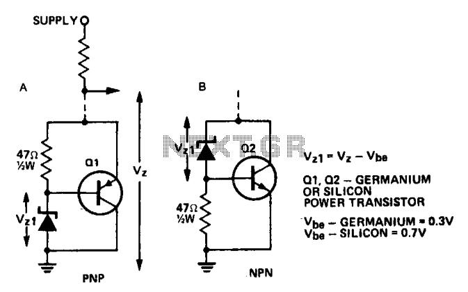
A power transistor can be utilized to supply a high-powered Zener voltage from a low-wattage Zener diode. A 400 mW Zener diode can be employed in applications requiring a 10-watt Zener, or a 1 W Zener can be used...
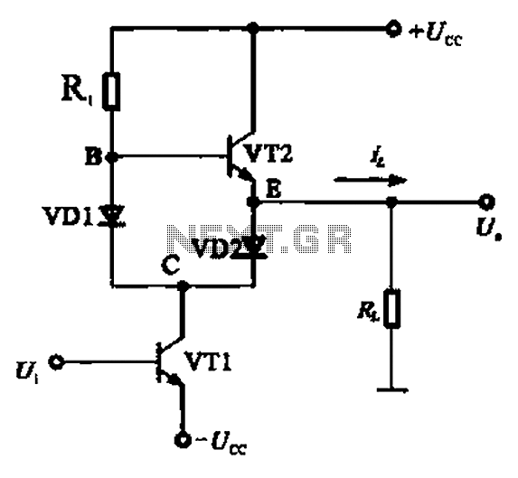
A Class AB output stage circuit is coupled with diodes, as illustrated in Figure 10-8. The static bias circuit for transistor VT1 (not shown) is adjusted so that the output at point E is at ground DC voltage UE....
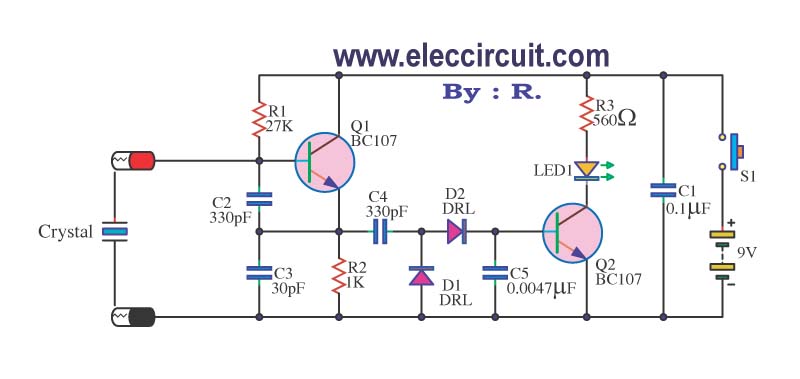
A multimeter cannot be used to test a crystal oscillator. Instead, a dedicated circuit is required, capable of checking crystals within the frequency range of 100 kHz to 900 MHz. This circuit is easy to construct and cost-effective. To construct...

This circuit is designed to prevent further damage to old equipment that may be in unknown condition, particularly to devices that are already shorted. The circuit functions as a protective measure for vintage or malfunctioning electronic devices. It is particularly...
This circuit utilizes the well-known and easily accessible LM3914 integrated circuit (IC). The IC is straightforward to operate, requiring no external voltage regulators due to its built-in voltage regulation capability, and can be powered by a variety of sources....
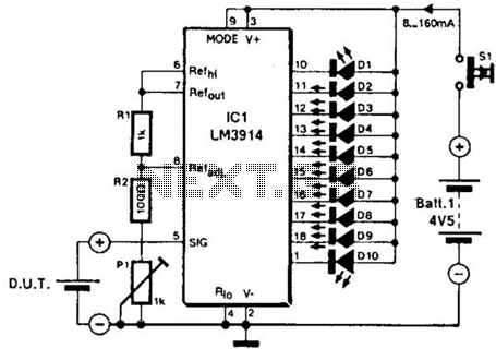
The LM3914A bar graph LED is utilized as a voltmeter for testing batteries. This circuit operates on a 4.5-V battery and compares the battery under test with an internally generated reference, established by resistors R1, R2, and potentiometer P1....