
Diode feedback comparator

The described circuit is primarily designed to maintain a constant current output for driving LED displays, which is crucial for ensuring consistent brightness and performance across varying supply voltages. The operational voltage range of 4V to 30V provides flexibility in applications, allowing the circuit to adapt to different power supply conditions without affecting the performance of the LED display.
The use of high-value resistors, specifically 10MΩ for R2 and R3, contributes to the high input impedance of the circuit. This characteristic is particularly advantageous in applications where minimal loading on the preceding stage is necessary, such as in sensor interfacing or signal conditioning applications. The high input impedance ensures that the circuit does not significantly alter the voltage levels of the signals it is meant to drive.
The grounding of the inverting input of the comparator is a crucial design choice that establishes a reference point for the feedback loop. This configuration allows for precise control over the output current, ensuring that it remains constant despite variations in the supply voltage or load conditions. The comparator plays a vital role in maintaining the desired output current by comparing the output voltage to a reference voltage, adjusting the output as needed to stabilize the current.
In addition to driving LED displays, this circuit can be adapted for various applications requiring a stable and controllable current source. Such applications may include powering sensors, driving small motors, or any system where consistent current is necessary for reliable operation. The versatility of this circuit makes it a valuable component in many electronic designs where current regulation is critical.This circuit can drive anLED display with constant current independently of wide power supply voltage changes. It can operate with a power supply range of at least 4V to 30V. With 10M resistances for R2 and R3 and the inverting input of the comparator grounded, the circuit becomes an LED driver with very high input impedance
The circuit can also be used in many other applications where a controllable constant current source is needed.
Related Circuits
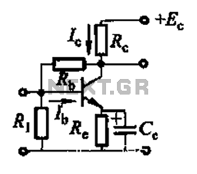
Basic reference transistor bias circuit - Mixed Negative feedback The basic reference transistor bias circuit utilizing mixed negative feedback is a fundamental electronic configuration designed to stabilize the operating point of a transistor. This circuit typically employs a combination of...
The diode tube under examination is essentially Edison’s early incandescent bulb containing a plate. The term "diode" refers to the two elements or electrodes within the glass container that constitute the tube. Shortly after the discovery of the Edison...
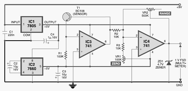
This digital thermometer circuit diagram uses a common 1N4148 diode as the temperature sensor. The temperature coefficient of the diode is -2 mV/°C. The digital thermometer circuit leverages the characteristics of the 1N4148 diode, which has a well-defined temperature coefficient....
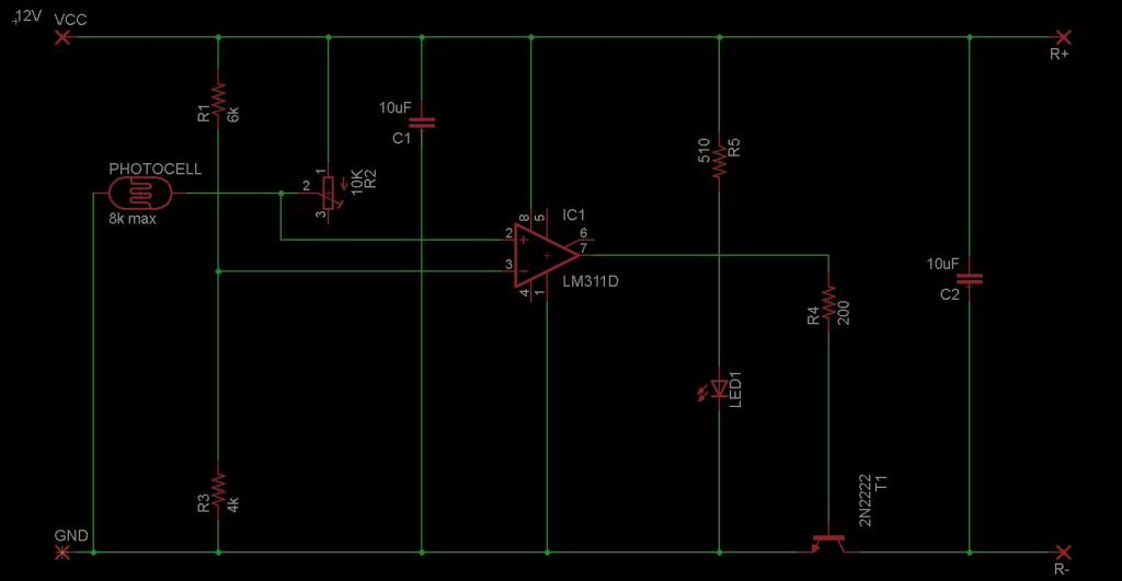
The circuit is designed to sense ambient light levels and activate lights when it is dark. A prototype was successfully built on a breadboard using an LM324 comparator, various resistors, a trimmer resistor, and a photocell. Subsequently, a PCB...

A photodiode can be utilized for high-speed digital transmission; however, it is necessary to provide a high-speed signal conditioner for this purpose. The amplifier circuit... A photodiode is a semiconductor device that converts light into electrical current. In high-speed digital...
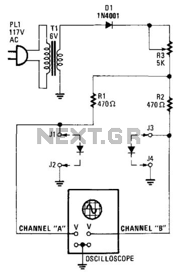
Suitable for matching diodes or examining the VI characteristics of two-terminal devices (such as diodes), this circuit is designed for laboratory use. Resistors R1 and R2 can be increased in value, and a higher voltage transformer can be utilized...