
Diode digital thermometer circuit

The digital thermometer circuit leverages the characteristics of the 1N4148 diode, which exhibits a predictable voltage drop that varies with temperature. As the temperature changes, the forward voltage drop across the diode decreases at a rate of approximately 2 mV for every degree Celsius increase in temperature. This property allows the diode to function effectively as a temperature sensor.
In the schematic, the 1N4148 diode is connected in a forward-biased configuration. The output voltage from the diode is fed into an analog-to-digital converter (ADC), which translates the analog voltage signal into a digital format suitable for further processing. The ADC is typically integrated into a microcontroller or a dedicated digital thermometer chip.
The circuit may also include additional components such as resistors and capacitors to stabilize the readings and filter out noise. A reference voltage source is often employed to calibrate the output of the ADC, ensuring accurate temperature readings. The microcontroller processes the digital signals received from the ADC and can display the temperature on an LCD or LED screen, or transmit the data wirelessly for remote monitoring.
Overall, this digital thermometer circuit is a cost-effective and straightforward solution for temperature measurement, leveraging the well-documented properties of the 1N4148 diode.This digital thermometer circuit diagram uses a common 1N4148 diode as the temperature sensor. The temperature coefficient of the diode, -2 mV / 0C is expl. 🔗 External reference
Related Circuits
This circuit operates as a 9V DC power source supplying a 555 timer to generate a square wave. The output is then processed through a Half-Wave Series Multiplier (Villard Cascade) to achieve a high voltage DC output. The goal...

The IR Jammer is a fun project that provides a bit of safe, non-destructive fun. The Infrared Remote Control Jammer allows you to render all IR remote controls inoperative! The microcontroller in this design allows for all 6 of...
This series-feedback configuration of compounds provides a high input impedance and stable, wide-band gain video amplifier suitable for general-purpose applications. It features low capacitance and high impedance. The described video amplifier circuit utilizes a series-feedback topology to achieve high input...
The circuit for the power amplifier has a power output of up to 1500W RMS and is commonly utilized in outdoor sound systems. The final image displays a series of power amplifiers that utilize 10 sets of power transistors....
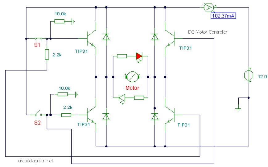
This is a DC motor controller circuit built using the TIP31 transistor based on the H-Bridge concept. The switches S1 and S2 are normally open, push-to-close buttons. The LED serves to indicate the direction of motor rotation and any...
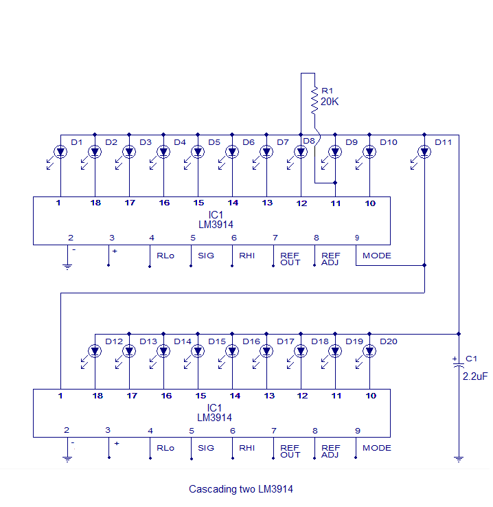
The core of this circuit is the LM3914 from National Semiconductor. The LM3914 is capable of sensing voltage levels and can drive a display of 10 LEDs in either dot mode or bar mode. The selection between bar mode...