
Infrared Remote Control Jammer circuit

The IR Jammer circuit employs a PIC 12F675 microcontroller as its core component, which is programmed to generate signals at six different infrared frequencies: 30kHz, 33kHz, 36kHz, 38kHz, 40kHz, and 56kHz. This versatility enables the device to disrupt a wide range of consumer electronics that utilize infrared communication, such as televisions, air conditioners, and other remote-controlled devices.
The circuit design includes four infrared LEDs—two narrow beam and two wide beam types. This configuration enhances the effective range and coverage of the emitted infrared signals. The use of two types of LEDs allows for both focused and dispersed transmission of the jamming signals, ensuring that the device can operate effectively in various environments.
Power management is a significant feature of the IR Jammer. The microcontroller enters a low-power sleep mode after initialization, significantly extending battery life. The device is awakened by a pin change interrupt, which can be triggered via a PCB mounted push button or an external switch connected to the On Sw. pads. This design allows for flexible mounting options, such as integration into existing remote controls or portable applications like hats.
The circuit also includes a green LED indicator that serves dual purposes: it blinks three times upon power-up to confirm operation and flashes periodically to indicate that the jammer is actively transmitting signals. The addition of selectable power resistors allows users to fine-tune the balance between operational range and power consumption, enabling customization based on specific usage scenarios.
Overall, the IR Jammer circuit represents an innovative approach to infrared signal disruption, combining user-friendly features with efficient power management and robust performance across multiple IR frequencies.The IR Jammer is a fun project that provides a bit of safe, non-destructive fun. The Infrared Remote Control Jammer allows you to render all IR remote controls inoperative! The microcontroller in this design allows for all 6 of the main IR frequencies to be targeted making this unit universal. It works by corrupting the data that is being sent by your normal remote controls. A single press of the button sends out stream of IR pulses from the two narrow beam and two wide beam IR LEDs for 30 seconds.
Each press of the button will add 30 seconds to the running timer. For remote operation you can simply connect a button to the On Sw. pads, shorting this input will turn on the IR output until the contact is opened. This would allow the device to be mounted into an old remote, brim of a hat, etc. The compact design is the size of a 9 volt battery allowing it to be strapped directly to its power source if desired. The heart of the IR Jammer is a PIC 12F675 microcontroller. This microcontroller has been programmed to reproduce the 6 popular IR frequencies, 30kHz, 33kHz, 36kHz, 38kHz, 40kHz and 56kHz.
When the button is pressed two transistors are used to pump infrared data out of the 4 IR LEDs. Using two wide beam and two narrow beam IR LEDs allows good distance and a ease of use. The Green LED is used to indicate power up by blinking 3 times and also to indicate when the jammer is running by a quick flash ever few seconds. When building the kit you can select the power selection resistors to adjust the balance between range and power consumption.
After the jammer flashes the green LED to indicate power on the unit goes to sleep and wakes up on a pin change interrupt, this allows it to last a very long time in standby. The PCB mounted push button will wake it up and allow it to operate for 30 seconds for each press and the On Sw.
remote switch connection will run the jammer until the switch is turned off. There are 6 assembly language routines that are used for each of the IR jamming frequencies that the device replicates. 🔗 External reference
Related Circuits

This tracking transmitter consists of four distinct subassemblies: a free-running multivibrator, a transmit switch, an audio-tone generator, and an FM transmitter. The multivibrator, which produces a pulse width with a pulse separation of 1500 ms, is built around Q1...
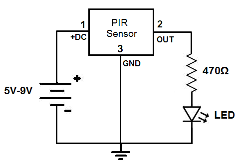
This circuit is designed to detect motion or movement, with its most common application being the detection of a person moving through an area covered by the motion detector. The primary electronic component utilized for this detection is the...
Boiling water or cooking with a gas stove can sometimes lead to the fire being extinguished due to water spills, which can result in a significant gas overflow and pose a risk of poisoning. This example describes a stall...

The technical parameters of high-speed optocouplers include a rise time (t1) of less than or equal to 300 ns, a circuit transfer ratio (CTR) of 50%, an isolation voltage (VSO) of at least 15,000 V, and an output transistor...

An ultra-simple circuit of the tilt sensor alarm can be fabricated using readily available, inexpensive components. The circuit operates as a true transistor-based design. The tilt sensor alarm circuit utilizes a tilt sensor, which is a device that detects the...

A Power Factor Correction (PFC) board has been obtained from an old Sun Microsystems Spark450 power supply (part number 300-1359-xx). This board contains all necessary components for a 650-watt inverter. However, the complete PFC circuit is not fully detailed...