
Comparator light sensor

The circuit operates based on a light-dependent resistor (photocell) that changes resistance according to the intensity of ambient light. In low-light conditions, the resistance of the photocell increases, allowing the comparator (LM311 in this case) to compare the voltage across the photocell with a reference voltage set by the resistors and trimmer. The output of the comparator switches states based on this comparison, ideally turning on the connected lights when it is dark.
The issue of oscillation and high-frequency noise may stem from the feedback loop or the configuration of the components. When the light is present, the photocell's resistance decreases, potentially causing rapid fluctuations in the output voltage due to insufficient damping in the circuit. This can result in the high-pitched hum observed. To mitigate this, employing multiple photocells oriented in various directions can provide a more stable input to the comparator, effectively reducing the likelihood of false triggering and oscillation.
Using a logic AND configuration would require each photocell to be connected to its own comparator, with their outputs combined to ensure that the lights only turn on when all conditions indicate darkness. This approach enhances reliability by ensuring that the system does not activate under false light conditions.
Regarding the transistor configuration, placing the 2N222 NPN transistor on the high side allows for better control of the load when the output from the comparator is high. If a low-side configuration is preferred, switching to a PNP transistor is advisable, but this requires a corresponding adjustment to the inputs of the comparator to ensure proper operation.
In summary, the circuit can be improved by addressing the oscillation issue through component configuration and by utilizing multiple sensors to enhance reliability in detecting ambient light levels. These adjustments will likely lead to a more stable and effective light-sensing and activation system.Sense the amount of ambient light and switch the lights on when it was dark out. I was successful in building one on a bread board that used an lm324 (its the only comparator radioshack had) some resistors a trimmer resistor and a photocell. So I went and designed a board using the same basic circuit but I replaced the lm324 with a lm311 and made a board.
However it dose not work smoothly when I have light shining on the photocell I hear a high pitched hum and i`m getting around 5. 6volts on the output when I block the light the humming goes away and the output goes up to 12v like it should. Ii am not sure how to fix it. i do not own an oscilloscope so i cant check but i`m guessing its oscillating when there is light and that`s why i hear the humming Any input on how I could fix this would be appreciated.
Thank you. use multiple photocell that sense every different direction and use logic AND to turn the light ON, the probability of hum and false OFF will be lower. the only condition thats surefire to trigger all condition TRUE is during the daylight. 2) put the 2N222 NPN on high 12V side, or change to PNP if you want to stick to that low side config (but you`ll also need to switch comparator +ve and -ve input), NPN works better on high side and PNP on low side (you got them backward in your schematics).
thats what my experience tells from my unproven experimenting. 🔗 External reference
Related Circuits
A compact and intriguing circuit designed to flash automotive headlights. It utilizes a well-known NE555 timer circuit to achieve this functionality. The circuit operates by employing the NE555 timer in astable mode, which allows it to generate a continuous square...
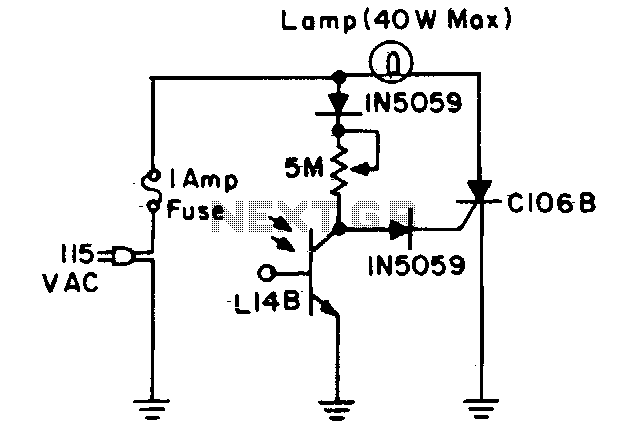
During daylight hours, the L14B photo-Darlington (registered as 2N5777 through 2N5780) shunts all gate current to ground. At night, the L14B effectively provides a high resistance, diverting the current into the gate of the C106B and turning on the...
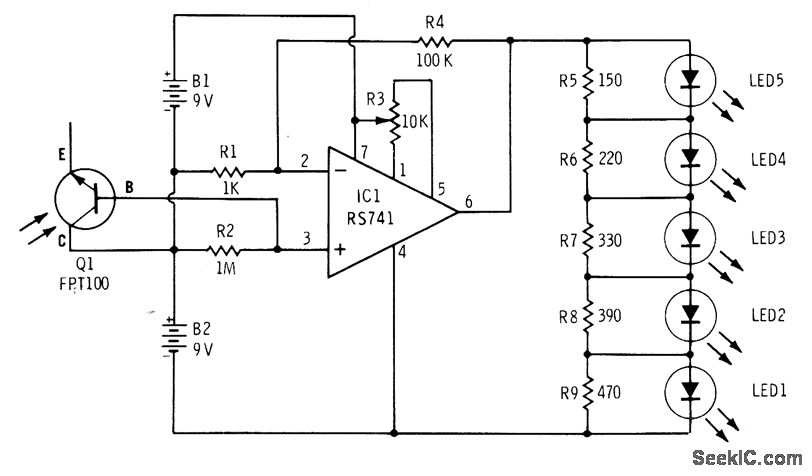
The phototransistor Q1 (Radio Shack 276-130) activates a voltage change across resistor R2, which is then amplified by an operational amplifier (op-amp). The output from the op-amp drives an array of five LEDs, creating a bar graph voltage indicator....
This circuit is a two-wire light level detector. The power supply and output signal are delivered through the same wires, utilizing a current loop. This two-wire light level detector circuit operates by using a single pair of wires for both...

This liquid level sensor circuit employs a common operational amplifier IC 741 configured as a comparator. When the sensor detects that the two fluid levels (which can be represented by two small pieces of PCB or similar conductors) are...
The objective of this project is to create a controller-based model that counts the number of individuals entering a specific room and activates the lighting accordingly. A sensor will be utilized to determine the current number of persons present....