
Direct Coupled Discrete Astable Multivibrator circuit

The described circuit operates as an astable multivibrator, utilizing two NPN transistors configured in a feedback loop. Each transistor's base is connected to the collector of the other, creating a regenerative feedback mechanism essential for continuous oscillation. The capacitors in the emitter circuits play a crucial role in determining the timing characteristics of the oscillation. Specifically, they charge and discharge, causing the transistors to switch states alternately.
In this configuration, the triangle wave output is generated due to the charging and discharging cycles of the capacitors, which control the timing of the transistor switching. The frequency of the oscillation can be adjusted by varying the capacitance of the capacitors or the resistances in the circuit. The use of a single 0.1 µF capacitor simplifies the design, reducing component count while maintaining the functionality of the circuit.
The output can be taken from the emitters of the transistors, where the triangle wave can be utilized in various applications, such as waveform generation, signal modulation, or as a clock signal in digital circuits. Proper biasing of the transistors is essential to ensure they operate in the active region, allowing for stable oscillation without distortion in the output waveform. The circuit's simplicity and effectiveness make it a popular choice for generating oscillating signals in electronic applications.This flip-flop circuit is a free running/astable multivibrator one, with bases and collector of both emitter biased transistor are directly coupled to each other. Switching action is supported by means of capacitor in each emitter circuit. This configuration produce a triangle waves at emitters. Since neither transistor can remain permanently cut off, then a free running oscillation will be generated. We can use single 0. 1 uF capacitor between emitters in place of C1 and C2. 🔗 External reference
Related Circuits
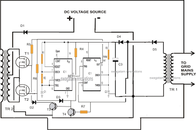
A single IC 556 has been utilized to generate PWM pulses. One half of the IC is configured as a high-frequency generator, which supplies the other half of the IC, set up as a pulse width modulator. The modulating...
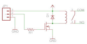
Before proceeding with the toaster oven reflow oven project, it is essential to understand the operation of relays and how to construct a simple relay breakout board. This discussion will focus on the design of a relay breakout board...

A replication of the Afrotechmods laser tripwire circuit utilizing a simple laser pointer, an IRF244 MOSFET (most NPN transistors would also suffice), a few resistors, and one light-dependent resistor (LDR). The Afrotechmods laser tripwire circuit is an innovative application of...
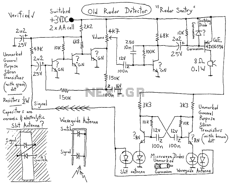
This integrated circuit (IC) requires fewer external components, making it simpler for beginners to assemble it on a veroboard. The original circuit was sourced from its datasheet. A slightly modified version of the circuit is presented below. This circuit...
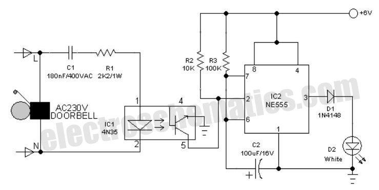
An interesting hobby circuit of a crank doorbell. The circuit is built around a 555 timer and a musical piezo buzzer. It operates using a 9-volt battery supply; a single 9-volt PP3/6F22 compact battery is sufficient to power the...
Convert a used CFL into a power-saving LED lamp circuit that consumes only 50mA. This gadget can be used in applications like a night light, table lamp, etc. The project involves redesigning a compact fluorescent lamp (CFL) to function as...