
A simple LED lamp circuit from scrap. Uses 5 LED and takes only 50 mA

The project involves redesigning a compact fluorescent lamp (CFL) to function as an energy-efficient LED lamp. The primary objective is to create a circuit that operates at a low current of 50mA while providing sufficient illumination for various applications, such as night lights or table lamps.
To achieve this, the circuit will utilize a suitable LED driver circuit that regulates the current flowing through the LED. The circuit should include a rectifier to convert AC to DC, as well as a voltage regulator to maintain a stable output voltage suitable for the LEDs. A common approach is to use a buck converter or a constant current source to ensure that the LED operates within its specified current range.
The design will also incorporate a heat sink to dissipate any excess heat generated by the LED during operation, ensuring longevity and reliability. The use of a microcontroller or a simple timer circuit can facilitate features such as dimming or automatic shut-off to enhance energy savings.
The LED array should be selected based on the desired brightness and color temperature, ensuring that the total forward voltage matches the output of the driver circuit. Proper thermal management and electrical isolation will be critical to ensure safety and efficiency.
Additionally, the enclosure for the modified lamp should be designed to allow for adequate ventilation and heat dissipation while maintaining an appealing aesthetic suitable for home decor. Overall, this project aims to provide a sustainable lighting solution by repurposing existing CFLs, thus reducing waste and promoting energy efficiency.Convert a used CFL into a power saving LED lamp circuit that consumes only 50mA. This gadget can be used in applications like night light, table lamp etc.. 🔗 External reference
Related Circuits
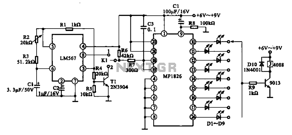
A precision circuit utilizing the LM567 timer, specifically the MPI826, where the LM567 functions as a dual-band oscillator. The MP1826 serves as a divider in the circuit, allowing the output signal from the LM567 to achieve extended timing. The...
A crystal oscillator circuit is a straightforward oscillator circuit that can be easily understood through its schematic diagram. It serves as a replacement for a conventional oscillator network, which typically consists of an LC combination. This simplicity is also...
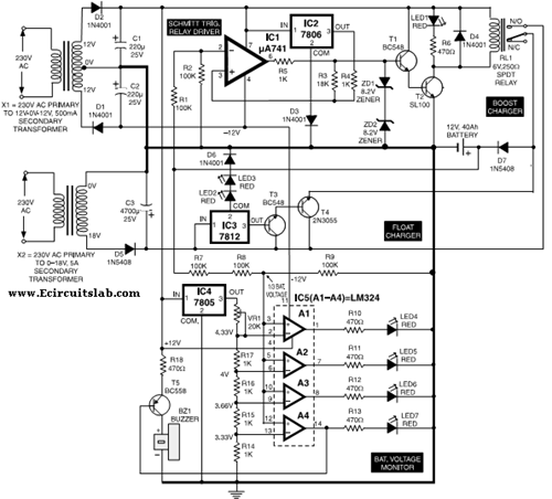
This circuit illustrates the use of the 7806 IC in an automatic battery charger circuit diagram. It is designed for a car battery with an approximate rating of 40 Ah. The automatic battery charger circuit utilizing the 7806 integrated circuit...
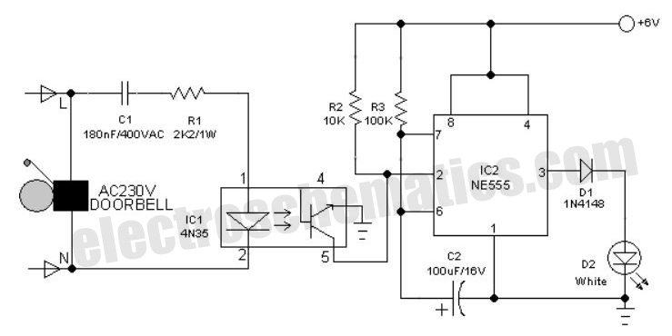
An interesting hobby circuit of a crank doorbell. The circuit is built around a 555 timer and a musical piezo buzzer. It operates using a 9-volt battery supply; a single 9-volt PP3/6F22 compact battery is sufficient to power the...
The Adjustable Timer circuit initiates timing upon activation. A green LED illuminates to indicate that timing is in progress. Once the designated time period elapses, the green LED turns off, the red LED activates, and an audible bleeper sounds....
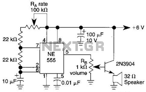
Ra sets the rate while RH sets the volume of clocks in the speaker. The 555 is configured as a low frequency oscillator. The circuit is powered by a 6 V battery. The circuit utilizes a 555 timer IC configured...