
Discharge time relay circuit

The discharge time relay circuit is designed to provide a controlled delay in activating or deactivating a load, utilizing a combination of resistors and capacitors to achieve precise timing. The field effect transistor (FET) serves as the primary timing element, allowing for high accuracy due to its low input capacitance and high input impedance.
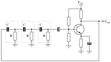
In this configuration, the resistor R3, which is set to 1,000,000 ohms, works in conjunction with the capacitor C, rated at 200 microfarads, to create a time constant that governs the discharge time. The relationship between the resistance, capacitance, and time constant can be expressed using the formula τ = R × C, where τ is the time constant in seconds. For the given values, τ would be approximately 200 seconds, which indicates the time it takes for the capacitor to discharge to about 37% of its initial voltage. However, the total delay time for the relay activation is further influenced by any additional resistance introduced by RP.
The operation begins when the user presses button SB, which activates transistor VT1. This action allows current to flow through the circuit, turning on transistor VT3, which in turn energizes relay KA. The relay's activation can control various loads, such as motors or lamps, based on the desired application.
As the capacitor C discharges, its voltage gradually decreases. When this voltage drops to a predetermined threshold, transistor VT2 switches from an off state to an on state. This transition causes transistor VT3 to turn off, effectively deactivating relay KA and stopping the load. The timing accuracy of this circuit is primarily determined by the stability of the capacitor and the resistors, making it suitable for applications requiring long delay intervals, such as in industrial automation, lighting control, and HVAC systems.
In summary, the discharge time relay circuit is a robust solution for implementing time delays in electronic systems, leveraging the characteristics of field effect transistors and passive components to achieve reliable performance over extended periods.Discharge time relay circuit The timer field effect tube, and therefore have a high timing accuracy, timing and so long. When the R3-IOOOMfl, C 200VF when a delay time of 8h. P ress the button SB, transistor VTi conduction, VT3 conduction, the relay pull KA, delay start. When the capacitor C discharges to a certain value, VT2 is turned on from off, VT3 deadline, KA released. Delay time is determined by R3, RP and C.
Related Circuits
This circuit can be used for detecting infrared light; for example, it is utilized for detecting infrared band light signals in a spectrophotometer. The amplifier output voltage Vo is given by the formula Vo = Is·Rd·Rf/Ri, where Is is...
The circuit utilizes a quad voltage comparator (LM339) as a basic bar graph meter to display the charge status of a 12-volt lead-acid battery. A 5-volt reference voltage is applied to each of the positive (+) inputs of the...

A simple battery charger designed for Nickel Metal Hydride batteries that require current-regulated charging. The charger delivers a charging current of 140 mA for efficient battery charging. The power supply section includes a 0-18 volt AC 1 Ampere step-down...
For successful circuit-building exercises, follow these steps: Measure and record all component values before constructing the circuit, selecting resistor values that are sufficiently high to minimize the risk of damaging any active components. In case of significant errors (greater...
This amplifier is designed for outdoor installation and is connected to an indoor power line box. It utilizes either 50-ohm or 75-ohm coaxial cables for the connection between indoor and outdoor units. The amplifier circuit board is depicted in...
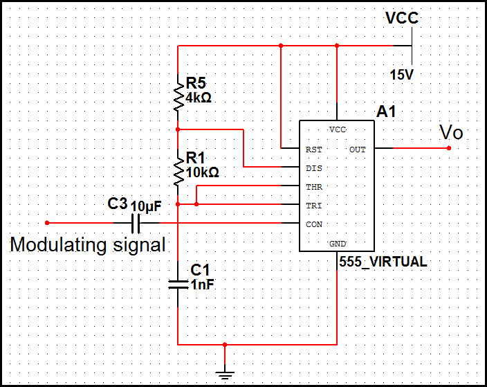
In pulse position modulation, the amplitude and width of the pulses are kept constant, while the position of each pulse with reference to the position of the reference pulse is changed according to the instantaneous sampled value of the...