
NiMH Battery Charger Circuit

The battery charger circuit described utilizes a transformer to step down the AC voltage, which is then rectified by the full-wave bridge rectifier. This configuration ensures that the output voltage is always positive, suitable for charging the battery. The smoothing capacitor C1 filters the rectified output voltage, reducing ripple and providing a stable DC voltage to the subsequent circuit components.
The current regulation mechanism is critical for the safe charging of Nickel Metal Hydride batteries, which can be damaged by excessive current. Resistor R1 is strategically chosen to set the desired charging current at 140 mA. The Epitaxial Darlington transistor TIP 127 is selected for its high current gain, allowing it to effectively control the output current with minimal input base current.
The LED indicator is a vital feature of the circuit, providing visual feedback regarding the charging status. When a battery is connected, and the input voltage is adequate, the LED illuminates, signaling that the charger is operational. The combination of R2 and the LED ensures that the base current to T1 is maintained at an optimal level, preventing the transistor from going into saturation, which could lead to an uncontrolled increase in charging current.
Overall, this simple yet effective battery charger circuit exemplifies fundamental electronic principles, including voltage regulation, current limiting, and visual status indication, making it suitable for safely charging Nickel Metal Hydride batteries in various applications.A simple battery charger for the Nickel Metal Hydride battery that requires current regulated charging. The charger provides 140 mA current for quick charging of the battery. Power supply section consists of a 0-18 volt AC 1 Ampere step-down transformer, a full wave bridge rectifier comprising D1 through D4 and the smoothing capacitor C1.
Current regulation is achieved by the action of R1, R2 and the Epitaxial Darlington PNP transistor TIP 127. Resistor R1 keeps the charging current to 140 milli amperes. LED and resistor R2 plays an important role to control the base current of T1 and thus its output. Around 2. 6 volts drop develops across the LED which appears at the base of T1. Emitter base junction of T1 drops around 1. 2 volts. So 2. 6 1. 2 volts gives 1. 40 volts. So the current passing through R1 will be 1. 40 V / 10 = 0. 14 Amps or 140 Milli Amps. The LED act as the charging status indicator. LED lights only if the battery is connected to the output of circuit and the input voltage is normal.
🔗 External reference
Related Circuits
The ICL7107 is a 3 1/2 digit LED analog-to-digital converter (A/D converter). It features an internal voltage reference, high-isolation analog switches, sequential control logic, and display drivers. The ICL7107 is designed to convert analog signals into digital representations with a...
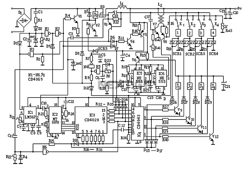
The circuit operates by sending ringing pulses through capacitor C1, resistor R1, and diode D2 to charge capacitor C2 to a voltage of 6V. This voltage causes transistors N1 and N2 to reverse, which activates V1, the analog hook,...
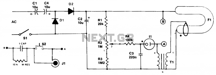
Initially, the neon and xenon lamps do not conduct and behave like very high (almost infinite) resistance. Capacitors C1 and C4, in conjunction with diodes D1 and D2, form a voltage doubler circuit, allowing C2 to charge up to...
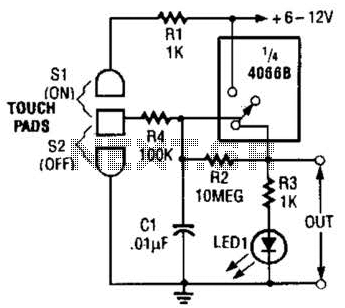
This touch-on switch can be activated through electrical means and can only be reset using a mechanical switch. When the touch terminal is activated by a finger, the SCR turns on and illuminates LED1. The circuit utilizes a silicon-controlled rectifier...
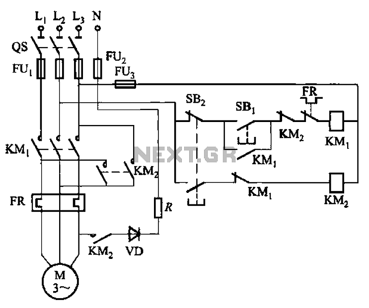
The circuit shown in Figure 3-139 utilizes a rectifier diode brake for neutral grounding in a three-phase, four-wire power supply system. The circuit employs a rectifier diode configuration to achieve effective neutral grounding, which is crucial for maintaining system stability...
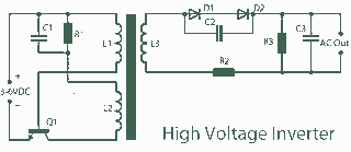
A 3V to 1000V inverter circuit has been constructed, but it is not functioning as intended. The creator seeks expert assistance to identify potential errors in the circuit design. Additionally, there is uncertainty regarding the transformer construction, as the...