
Light Dimmer Circuit

The described dimmer circuit employs a TRIAC (Q1) to regulate the power delivered to a load, such as a lamp or motor. The primary components include resistors R1 and R2, a variable resistor (potentiometer) VR1, and capacitors C2 and C3, which work together to establish the phase control necessary for dimming.
The operation begins with the charging of capacitor C2 through the resistors R1 and R2. The time constant for this charging process is influenced by the values of these resistors and the capacitance of C2. As VR1 is adjusted, it alters the resistance in the circuit, which in turn changes the charging time of C2. The voltage across C2 rises until it reaches a certain threshold, at which point it triggers the TRIAC.
The TRIAC conducts, allowing current to flow to the load. The point at which the TRIAC is triggered determines the phase angle of the AC waveform that is allowed to pass through to the load, effectively controlling the power delivered. This phase control is what enables the dimming function, as a later trigger point results in less power being delivered to the load.
Capacitor C3 may be included to filter out noise and stabilize the voltage levels in the circuit, ensuring reliable operation. Proper selection of the component values is crucial for achieving the desired dimming range and response time. Additionally, the circuit may benefit from protective components, such as a fuse or circuit breaker, to prevent damage from overcurrent conditions.
Overall, this simple dimmer circuit exemplifies an effective method for controlling AC power and can be applied in various lighting and motor control applications.The circuit below is a simple dimmer circuit. Network of R1, R2, VR1, C2, C3 and Q1 controls the triggering angle of the triac by varying the variable resistor VR1.. 🔗 External reference
Related Circuits
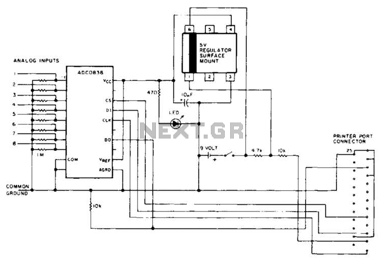
An A/D converter by National Semiconductor (ADC0838) converts 0 to 5 V analog inputs into a digital data format. A 9 V battery is utilized. The converter connects to the pointer port connector through a 25-pin connector. The ADC0838 is...
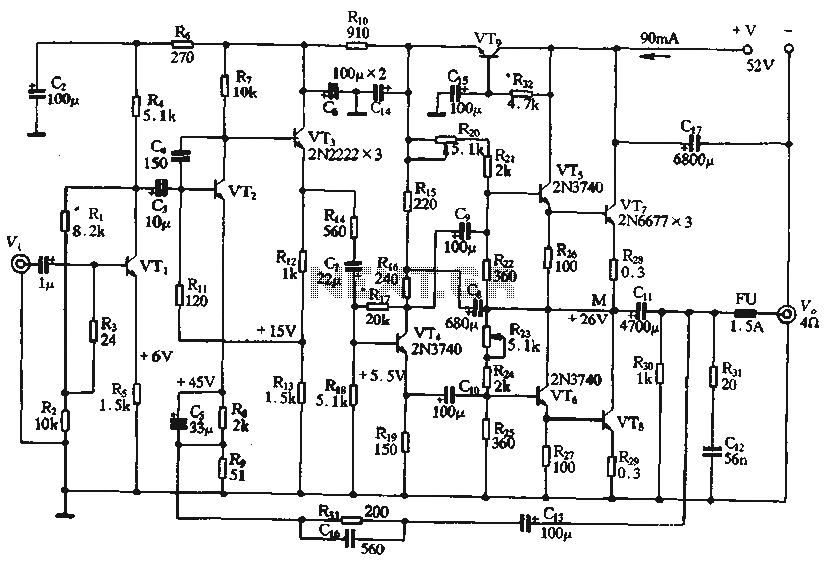
The circuit depicted in the figure is a highly technical OTL (Output Transformer-Less) amplifier circuit. It features a frequency response range of 10 Hz to 100 kHz and exhibits a total harmonic distortion of less than 0.1%, which is...
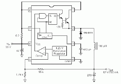
Switching regulator subsystems intended for use as DC to DC converters. 3V to 40 Volt DC Converter circuit. The use of switching regulators is becoming more pronounced than that of linear regulators because the size reductions in new equipment...
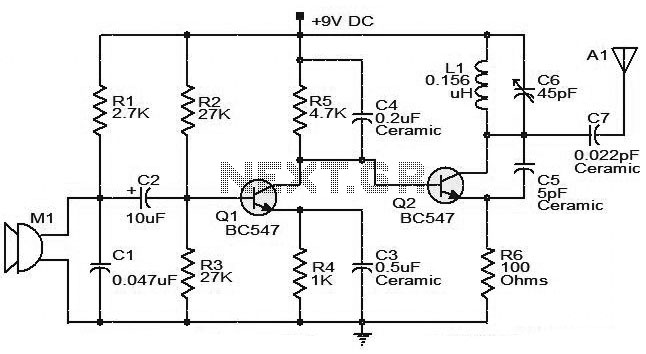
The moderate power FM transmitter circuit employs two transistors. The voice signals picked up by the microphone will be amplified by the transistor. The described FM transmitter circuit utilizes two transistors to facilitate the modulation and amplification of audio signals....
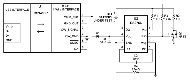
This characterization circuit, along with a PC and specific software, accurately measures the complete discharge cycle of a rechargeable AA cell. The capacity and output resistance of the cell can be easily determined from the resulting curve of these...
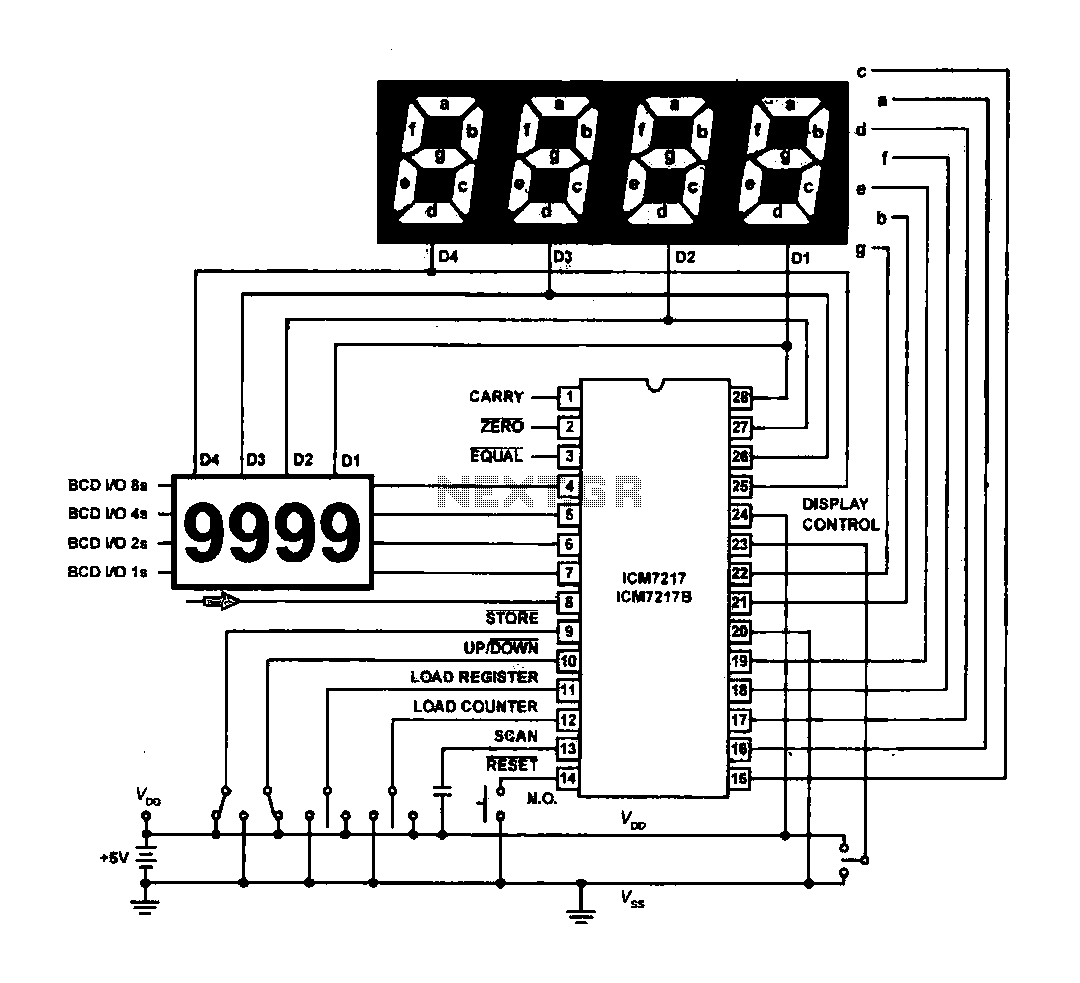
The circuit drives the light-emitting diode in a digital display configuration. The count signal is fed into the ICM7217 chip, which processes the count and subsequently drives the digital display board. The connection between the thumbwheel switches is illustrated...