
Mini Led Flashlight with LT1073 IC

The mini LED flashlight circuit typically consists of several key components: an LED, a resistor, a switch, and a rechargeable battery. The LED serves as the light source, while the resistor is used to limit the current flowing through the LED, ensuring it operates within safe parameters.
The circuit can be powered by a 1.2 V rechargeable battery, commonly a NiMH or NiCd type, which provides sufficient voltage for the LED to illuminate effectively. The switch allows the user to turn the flashlight on and off, providing convenience and control over the light output.
In a typical configuration, the LED is connected in series with the resistor and the battery. The value of the resistor is calculated based on the forward voltage rating of the LED and the desired current. For instance, if the LED has a forward voltage drop of 2.0 V and a recommended operating current of 20 mA, a resistor value can be determined using Ohm's law (R = (V_supply - V_LED) / I_LED).
The compact nature of this circuit allows for easy integration into small enclosures, making it suitable for portable applications. Proper thermal management should also be considered, as prolonged use of the LED may generate heat, potentially affecting performance and longevity.
Overall, this mini LED flashlight circuit represents an efficient and practical solution for portable lighting needs, combining simplicity with effectiveness in design.This led lamp circuit can be used as a mini led flashlight. Together with a 1.2 V rechargeable battery, all the components fit into a small enclosure. This.. 🔗 External reference
Related Circuits
A schematic of a flip-flop LED flashing circuit is presented. This circuit functions as an astable multivibrator that activates LEDs sequentially upon power application. It is compatible with voltage inputs ranging from 6 to 12 volts, and can also...
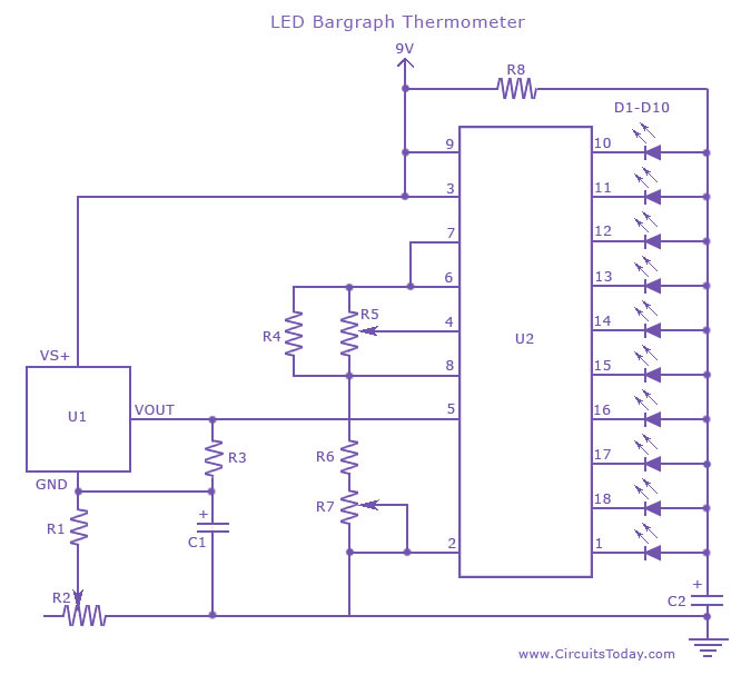
An LED thermometer that can function as a temperature sensor or temperature measurement circuit, utilizing the LM34 for Fahrenheit display or the LM35 for degree Celsius display. The LED thermometer circuit is designed to provide accurate temperature readings using either...

After constructing a Pulse Width Modulator for high-power LEDs, another LED modulator was developed for an optical transceiver. This project utilized a different approach, focusing solely on linear techniques for audio modulation. Similar to the PWM circuit, this circuit...

An integrated voltage regulator connected in reverse to a mini drill allows for speed adjustment within specific limits, maintaining a constant speed regardless of load. The electronic speed control is achieved through a voltage regulator, which can power motors...

This circuit can be utilized by individuals, such as a gentleman summoning his butler, a manager calling for his secretary, or, as in the author's case, to call children down for dinner without raising one's voice over the noise...

In this circuit, the 555 timer is utilized in an innovative manner as a voltage-controlled switch. The widely used NE555 can perform effectively in various applications. The 555 timer, a versatile integrated circuit, is commonly employed in timer, delay, pulse...