
Discrete 0.5-300 ms Monostable Multivibrator

The monostable multivibrator circuit operates by producing a single output pulse in response to a triggering event. The primary components involved include a capacitor, resistors, and transistors, which work together to define the duration of the output pulse. In this configuration, CR1 serves as a critical component that allows the input signal to control the operation of the circuit without directly influencing the output, thanks to its open collector configuration.
When the input signal is applied, CR1 activates TR1, which momentarily connects the input to ground. This action causes a change in voltage across the timing capacitor, which is charged through the resistor R5. The value of R5, in conjunction with the capacitor, determines the time constant of the circuit, thereby controlling the pulse width. The use of a 1M trimmer potentiometer allows for fine adjustments to the resistance, enabling precise control over the timing characteristics of the output pulse.
The output pulse is taken from the collector of TR2, which acts as the final stage of the circuit. The output can be utilized to drive other components or circuits, making this monostable multivibrator versatile for various applications, such as timers, pulse generation, or signal conditioning. The design ensures that the output remains stable and predictable, provided the input trigger is properly managed.
The schematic diagram accompanying the description illustrates the component layout and connections, providing a visual aid for understanding the circuit's functionality and interrelationships between components. This detailed overview emphasizes the importance of each component and their roles in achieving the desired pulse width and circuit behavior.Monostable multivibrator circuit produce a fixed pulse-width when the input is triggered. The input is fed to CR1, which should be an open collector source since the TR1 would short the input to ground during the active state appear on this circuit`s output. The output of this circuit is tapped from the collector of TR2. This monostable multivi brator output pulse width can be varied from 0. 5 to 300 milliseconds, adjusted by a 1M trimmer potentiometer R5. Here is the schematic diagram of the circuit: 🔗 External reference
Related Circuits
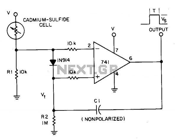
A photocell circuit provides automatic threshold adjustment. Monostable action prevents undesired retriggering of the output. With only one op amp IC, the circuit offers automatic adjustment of its trigger level to accommodate various light sources, changes in ambient light,...
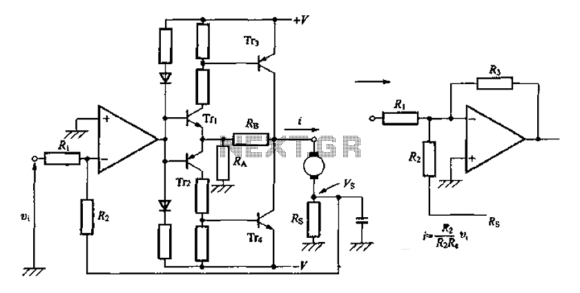
A discrete transistor current control circuit diagram. The discrete transistor current control circuit is designed to regulate the flow of current through a load by utilizing a transistor as the primary control element. This circuit typically consists of a few...
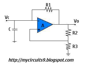
This circuit is also known as a Free Running Oscillator because it does not require any trigger pulse to become active. Consider the moment when Vc equals +Vsat. At this point, the capacitor charges exponentially towards +Vsat through resistor...
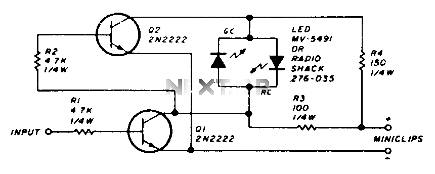
The circuit employs a dual LED configuration. When power is supplied to the probe through the power leads, and the input is connected to a low level or ground, transistor Q1 is turned off. This results in transistor Q2...
This circuit employs a protective resistor R2 along with a feedback resistor R1. Together, these components create a voltage divider that lowers the input voltage amplitude for IC1-a, ensuring that the protective diodes remain inactive. This arrangement enhances the...
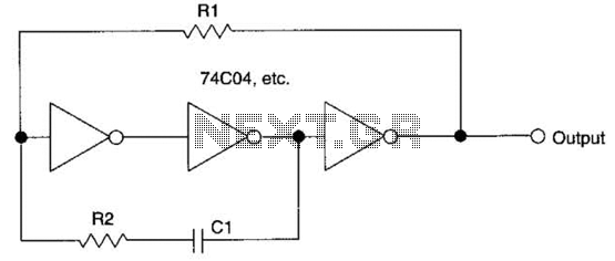
Electronics tutorial about multivibrators, including monostable multivibrator circuits, astable multivibrators, bistable oscillators, and clocks. Multivibrators are essential electronic circuits that generate specific output waveforms based on their configuration. They are classified into three primary types: monostable, astable, and bistable multivibrators....