
A discrete transistors from the current control circuit diagram of the way

The discrete transistor current control circuit is designed to regulate the flow of current through a load by utilizing a transistor as the primary control element. This circuit typically consists of a few key components: a power supply, a load (which could be a resistor, motor, or LED), a transistor (often a bipolar junction transistor or MOSFET), and a control mechanism, which may include a potentiometer or a fixed resistor for setting the desired current level.
In operation, the circuit begins with the power supply providing voltage to the load. The transistor acts as a switch or amplifier, allowing current to flow through the load when the base (or gate, in the case of a MOSFET) is activated by a control signal. The amount of current flowing through the load is determined by the voltage applied to the base/gate of the transistor, which adjusts the transistor's conductivity.
A feedback mechanism may also be incorporated into the circuit to enhance stability and accuracy. This can be achieved by using a resistor in series with the load to sense the current, feeding a portion of the current back to the base/gate of the transistor. This feedback loop helps maintain the desired current level despite variations in load resistance or supply voltage.
The schematic representation of this circuit typically includes the power supply voltage source, the load, the control resistor or potentiometer, the transistor symbol indicating its type, and any additional components such as capacitors for filtering or diodes for protection against reverse polarity.
Overall, this discrete transistor current control circuit is a fundamental building block in electronic design, enabling precise control of current in various applications, from simple LED drivers to complex motor control systems.A discrete transistors by the current control circuit diagram of the way
Related Circuits
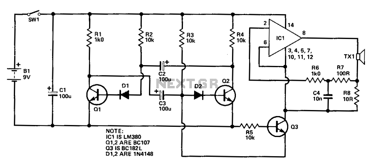
The circuit is a battery charging system powered by Q2, Q6, R8, and D10, which provides constant current to charge the battery. When an external power supply is present, the charging current flows through R8 and D10 to charge...
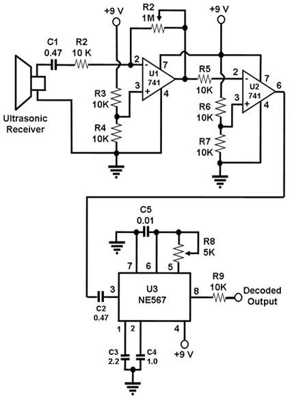
The ultrasonic receiver utilized in this circuit is specifically designed to vibrate optimally at a frequency of approximately 40 kHz. Consequently, the transmitter associated with this receiver must also emit waves at 40 kHz. When these waves interact with...
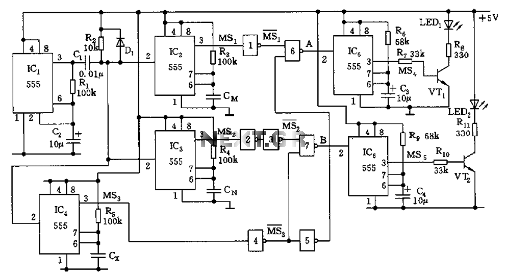
The capacitor filter operates by measuring the capacitance, which is proportional to the pulse width. This measurement is compared to a nominal capacitance to determine qualification. The circuit, as illustrated in the accompanying figure, includes IC1 along with resistors...
This circuit comprises two fundamental components: an oscillator tuned to 40 kHz and a voltage doubler with a pulse generator. The pulses generated are approximately 10 ms in duration and occur 2-3 times per second to minimize battery consumption...
A 2002 Blazer was diagnosed with error codes P0155 and P0756, indicating a malfunction in the O2 sensor heater circuit and a performance issue with the shift solenoid B circuit. The vehicle initially has power, but it loses power...
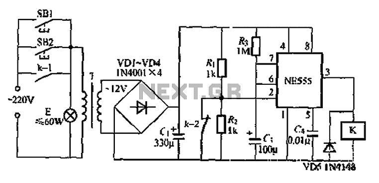
Another application involves the use of a NE555 delay lamp circuit, where components SB1 and SH2 act as J-light buttons that can be installed in two different locations. The lamp can be activated by pressing either SB1 or SB2,...