
ASTABLE MULTIVIBRATOR USING OP AMP

The Free Running Oscillator is a fundamental circuit used in various applications requiring periodic signals. It typically consists of a resistor (R), a capacitor (C), and an operational amplifier (op-amp) configured in a feedback loop. The operation begins with the capacitor charging through the resistor, which determines the time constant of the circuit. The charging phase continues until the voltage across the capacitor (Vc) reaches a threshold (in this case, +2Vsat), causing the output voltage (Vd) to switch states.
When Vd transitions to -Vsat, the capacitor discharges, leading to a decrease in Vc. This discharge phase continues until Vc falls to -2Vsat, at which point Vd again switches to +Vsat. The cycle then repeats, creating a square wave output. The frequency of oscillation can be adjusted by changing the values of the resistor and capacitor, allowing for flexibility in design.
This oscillator configuration is advantageous due to its simplicity and the absence of external triggering requirements. It can be used in applications such as clock generation, tone generation, and signal modulation, making it a versatile component in electronic design. The stability and frequency characteristics of the oscillator can be further refined through careful selection of components and circuit layout.This circuit is also called as Free Running Oscillator. Because, it doesn`t requires any trigger pulse to get active. Consider the instant at which Vc=+Vsat. Now the capacitor charges exponentially towards +Vsat through R. Automatically, Vd increases and crosses zero. This happens when Vc=+ ²Vsat. At the moment Vd becomes positive due to further charging of the capacitor. Output changes to -Vsat. Now capacitor starts discharging to zero and recharges towards -Vsat. Now Vd decreases and crosses zero. This happens when Vc=- ²Vsat. At the moment Vd becames negative again, output changes to +Vsat. This completes one cycle of output. 🔗 External reference
Related Circuits
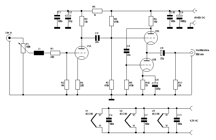
Because it seemed fun to me also try the so-called "high-end tube technique to highlight here, I agree with some parts from the stock went to work. A second point was that my family had enough of my taste...
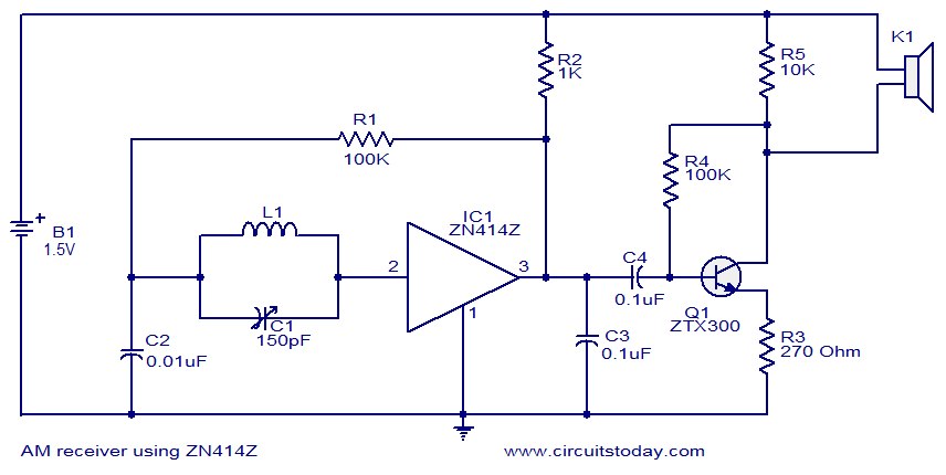
This circuit diagram represents a simple single-chip AM radio, designed around the ZN414Z integrated circuit (IC), which is a ten-transistor tuned radio frequency receiver. The IC features three leads and is housed in a TO92 package. It incorporates all...
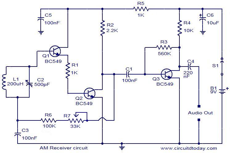
Circuit diagram of a modulator circuit in a transmitter and receiver of amplitude modulation. The modulator circuit in an amplitude modulation (AM) transmitter and receiver plays a crucial role in the process of encoding information onto a carrier wave. In...
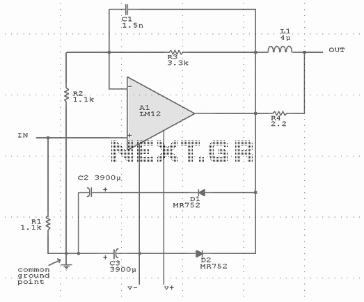
Output-clamp diodes are mandatory because loudspeakers are inductive loads. Output LR isolation is also used because audio amplifiers are usually expected to handle up to 2 mF load capacitance. Large, supply-bypass capacitors located close to the IC are used...
This circuit measures the cold cranking amps of a battery by discharging the surface charge and then assessing the internal resistance. This method provides a more accurate measurement than merely observing the instantaneous voltage drop under load. A constant-current...
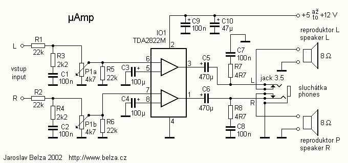
The amplifier is based on an integrated circuit TDA2822M. With this circuit, an amplifier can be built with up to 2 W. This much power circuit is able to supply only at peak times; continuous excitation would not be...