
Discrete PWM Generator Circuit

PWM (Pulse Width Modulation) is an effective technique for controlling the speed of DC motors by varying the average power delivered to the motor. The fundamental concept involves switching the power to the motor on and off at a high frequency, with the ratio of the "on" time to the "off" time (known as the duty cycle) determining the effective voltage and current supplied to the motor.
In a NE555-based PWM generator, the duty cycle can be adjusted by varying the resistance and capacitance in the timing circuit. The NE555 timer operates in astable mode to generate a continuous square wave output. By changing the resistor values or the capacitor, the mark-to-space ratio can be modified, thus controlling the motor speed effectively.
For applications requiring digital control, microcontrollers are commonly employed to generate PWM signals. The timer/counter modules within these microcontrollers can be configured to produce PWM outputs with precise duty cycles, allowing for fine control over motor speed. The programming of the microcontroller can be tailored to adjust the PWM frequency and duty cycle in response to user inputs or feedback from sensors.
In scenarios where a microcontroller is not used, discrete logic components such as flip-flops, resistors, and capacitors can be assembled to create a simple PWM generator. For instance, a 555 timer can be used in conjunction with a few discrete components to achieve similar functionality. Additionally, digital counters can be employed to create a PWM signal by toggling the output based on a defined count.
Overall, PWM is a versatile method for controlling DC motors, providing both analog and digital options for signal generation, and can be implemented in various ways depending on the specific requirements of the application.PWM waveforms are commonly used to control the speed of DC motors. The mark/space ratio of the digital wave-form can be defined either by using an adjustable analogue voltage level (in the case of a NE555 based PWM generator) or digitally using binary values. Digitally derived PWM waveforms are most often produced by the timer/counter modules in microcontrollers but if you do not want to include a microcontroller in your circuit it s also quite simple to generate the signals using discrete logic components..
🔗 External reference
Related Circuits
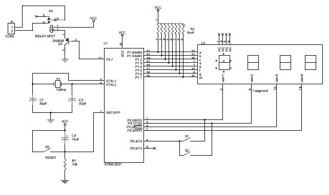
The circuit diagram above illustrates the Clock Controller V1.1. Pins P3.0 to P3.3 are connected to the base of a 4-PNP transistor, specifically the 2N2907, which is used to sink current. The Clock Controller V1.1 circuit is designed to manage...
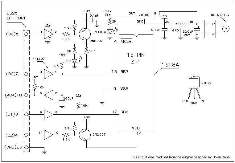
A universal Windows-based software designed to work with any serial programmers for the PIC16F84, known as WPicProg16 V1.20. It is recommended to build this programmer before starting various interesting projects with the F84. Some PIC programmers support in-circuit programming,...
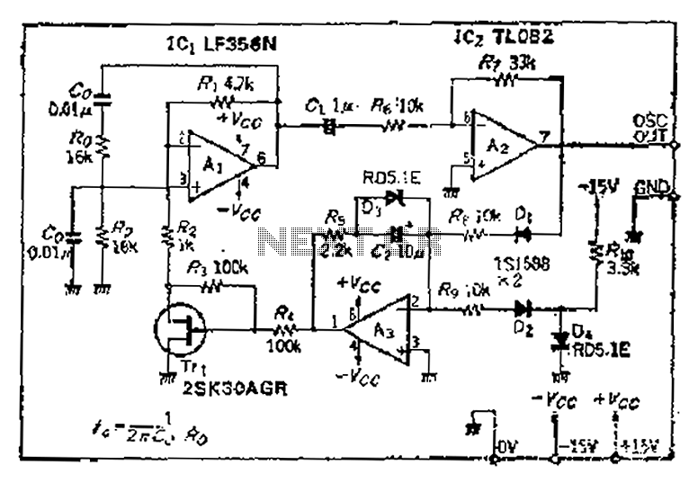
The intermodal servo preamplifier circuit operates at 115V and 60Hz, designed to provide a differential output for a servo motor amplifier. It features an inverting connection using an operational amplifier (op-amp), along with an additional op-amp configured to create...
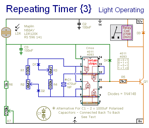
This circuit closely resembles Repeating Timer No. 2. However, the inclusion of a light-dependent resistor (LDR) allows the timer's operation to be confined to daylight hours. Resistor R7 enables the adjustment of the light level at which the timer...
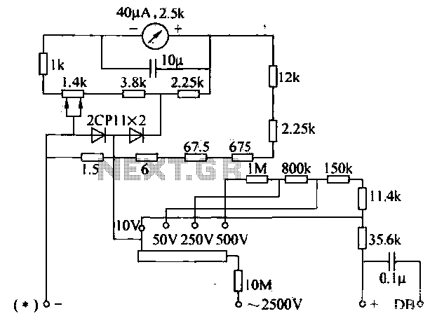
The voltage converter can be configured to switch between AC voltage ranges using a selector switch. The measurement circuit is depicted in the accompanying figure. In this configuration, a shunt resistor is placed in parallel with the header, maintaining...
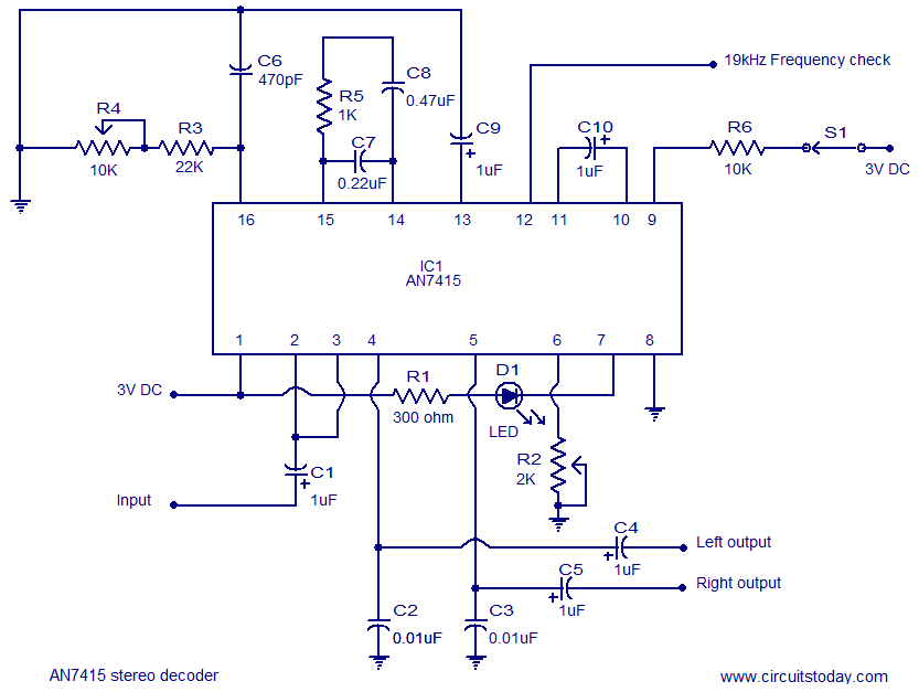
AN7415 based FM stereo demodulator circuit. 1.6 to 7V operating voltage range. High gain and low distortion. The AN7415 is a versatile integrated circuit designed for FM stereo demodulation applications. This circuit operates within a voltage range of 1.6 to...