
FM stereo demodulator circuit based on AN7415. 3V operation good channel seperation

The AN7415 is a versatile integrated circuit designed for FM stereo demodulation applications. This circuit operates within a voltage range of 1.6 to 7 volts, making it suitable for various portable and battery-operated devices. The high gain characteristic of the AN7415 ensures that weak FM signals can be amplified effectively, allowing for improved signal reception and clarity. Additionally, the low distortion feature of this circuit contributes to high-quality audio output, which is essential for stereo applications.
The typical configuration of the AN7415 in an FM stereo demodulator includes several key components. The input stage typically consists of an antenna connected to a tuning circuit that selects the desired FM frequency. This signal is then fed into the AN7415, where it undergoes demodulation to extract the audio information from the modulated carrier wave.
The circuit may also incorporate external components such as resistors and capacitors to set the appropriate gain levels and filter out unwanted frequencies, ensuring that only the desired audio signals are processed. Additionally, the output stage of the circuit can be designed to drive headphones or other audio output devices, providing a clear and distortion-free sound.
Overall, the AN7415 based FM stereo demodulator circuit is a robust solution for audio applications requiring high fidelity and efficient signal processing. Its simplicity in design and effectiveness in performance make it a popular choice among electronics engineers and hobbyists alike.AN7415 based FM stereo demodulator circuit. 1.6 to 7V operating voltage range. High gain and low distortion.. 🔗 External reference
Related Circuits
As the position of the sun changes, the illumination level on the light-dependent resistors (LDRs) also varies, causing the input voltage for the window comparator to deviate from half of the supply voltage. Consequently, the output of the comparator...
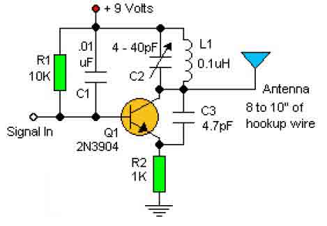
This basic RF oscillator circuit is easy to build and the components are not critical. Most of them can be found in your junk parts box. The L1 antenna coil can be made by close winding 8 to 10...
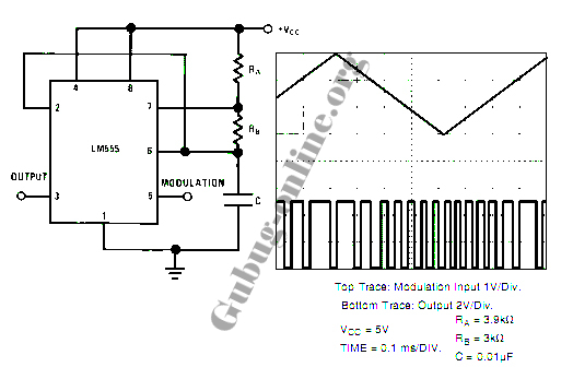
This design circuit for a pulse position modulator can be easily constructed using a 555 integrated circuit (IC). The pulse position modulator modulates the on-period while maintaining a fixed off-period. The circuit utilizes the 555 timer IC in astable mode...
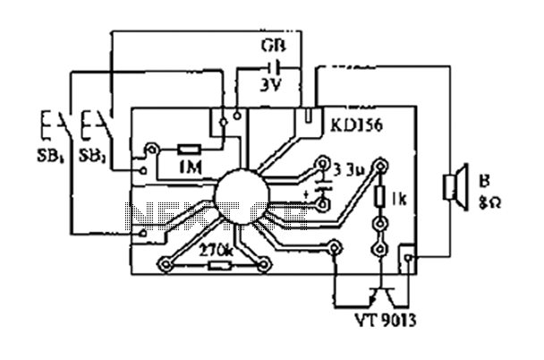
The analog sound KD156 produces a lingering "Ding Dong" sound reminiscent of birds singing, utilizing an integrated circuit. The KD156 is an analog sound generator designed to replicate natural soundscapes, particularly the soothing and familiar tones of birds singing. The...

The concept involves using infrared light that is reflected by a disc, except for a dark red line. The sensor receives the reflected light, allowing the Arduino to track the number of revolutions. The infrared sensor is tuned to...
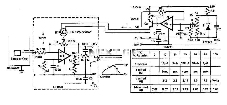
To amplify small current signals as an electron collector inside a vacuum chamber, it is advantageous for reasons related to noise and bandwidth to have a "head-amplifier" connected to the chamber. Operational amplifier 1 is a precision device featuring...