
diy blue beam dye laser

The flyback transformer operates by converting low-voltage DC into high-voltage DC, utilizing a specific driving frequency, in this case, 15 kHz. This frequency is crucial for the efficient operation of the transformer, as it determines the rate at which the magnetic field in the transformer core builds up and collapses. The flyback transformer is typically employed in applications requiring high-voltage outputs, such as in CRT displays, ignition systems, and various power supply circuits.
In operation, when the primary winding of the flyback transformer is energized at 15 kHz, it induces a magnetic field in the transformer core. During the "on" phase, energy is stored in the magnetic field. When the drive signal is turned off, the magnetic field collapses, inducing a high voltage in the secondary winding. The output is rectified and filtered to produce a stable high-voltage DC output.
The design of the circuit must consider components such as the primary and secondary windings, the core material, and the rectification method. The choice of these components will affect the efficiency, output voltage, and overall performance of the flyback transformer circuit. Proper consideration of the driving frequency and the circuit's load characteristics is essential to ensure optimal operation and prevent damage to the transformer or connected devices.No, wait.. the 15 KHz is the frequency that you use for drive the flyback transformer, is right, but the high voltage at the output is DC, cause.. 🔗 External reference
Related Circuits

The circuit below is similar to the one above but can be used with a laser pointer to toggle the relay rather than a push button. The IR photo transistor Q1 (Radio Shack 276-145A) or similar is connected to...

When the light beam that falls on the CDS photocell is interrupted, the transistor (EN3904) conducts, triggering SCR1 (CI06) and activating the alarm bell. SI resets the SCR. The alarm bell should be a self-interrupting electromechanical type. The lamp...
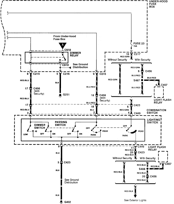
Grounding the blue wire at the headlamp switch causes the lights to illuminate, indicating a faulty switch. Continuity of the switch has already been verified. The relay consists of two small terminals and two larger ones. The smaller terminal,...

This DIY sound-activated lights circuit turns a lamp on for a brief duration when a dog barks or when a relatively loud sound is detected, creating the impression that the occupants are alerted. The condenser microphone is positioned to...

A voltage-controlled current source can be utilized to implement a laser diode driver. In comparison to switched (PWM) drivers, this simple linear laser diode driver offers distinct advantages. A voltage-controlled current source (VCCS) is a crucial component in driving laser...

One advantage of a solid-state relay (SSR) over a conventional electromagnetic relay (EMR) is its wear-free operation. The S201S01 from Sharp is a notable example. Solid-state relays (SSRs) are electronic switching devices that use semiconductor components to perform the switching...