
Toggle Flip Flop Laser Pointer Using CD4013

This circuit utilizes an infrared (IR) photo transistor, specifically the Q1 component, which is crucial for detecting the laser pointer's beam. The photo transistor is connected to the set input of a relay module, allowing for remote activation of the relay through the modulation of light. When the laser pointer illuminates the photo transistor, it generates a current that triggers the relay, effectively toggling it on or off depending on the duration of the laser exposure.
To ensure optimal performance, the photo transistor must be shielded from ambient light sources that could cause false triggering. This can be achieved by placing the photo transistor in a housing that blocks out unwanted light while still allowing the infrared light from the laser pointer to reach it. The circuit design should also include appropriate resistors to limit the current flowing through the photo transistor and protect it from damage.
Additional components may be included in the circuit to enhance functionality, such as a capacitor for noise filtering, or a diode across the relay coil to prevent back EMF when the relay is deactivated. The relay itself can control various loads, making this circuit versatile for applications such as remote switching, security systems, or automation projects. Proper attention to the layout and connections will ensure reliable operation and longevity of the circuit.The circuit below is similar to the one above but can be used with a laser pointer to toggle the relay rather than a push button. The IR photo transistor Q1 (Radio Shack 276-145A) or similar is connected to the set input (pin 6). The photo transistor should be shielded from direct light. 🔗 External reference
Related Circuits

A simple metal detector electronic project circuit can be designed using the CS209A integrated circuit manufactured by Cherry Semiconductor. The CS209A integrated circuit is a bipolar monolithic integrated circuit intended for metal detection and proximity sensing applications. It incorporates...

Application circuit using three stereo digital potentiometers to control volume, balance, and fader in a four-speaker configuration with a push-button interface. The application circuit utilizes three stereo digital potentiometers, which are essential components for managing audio levels in a multi-speaker...

A simple touch dimmer circuit diagram using the TT6061 IC, which is a touch control integrated circuit used for light dimmer circuits and lamp dimmer circuits. The touch dimmer circuit utilizing the TT6061 IC is designed to provide a user-friendly...

This 555 timer circuit toggles a relay when a button is pressed. Pins 2 and 6, the threshold and trigger inputs, are held at half the supply voltage by two 10K resistors. When the output is high, the capacitor...
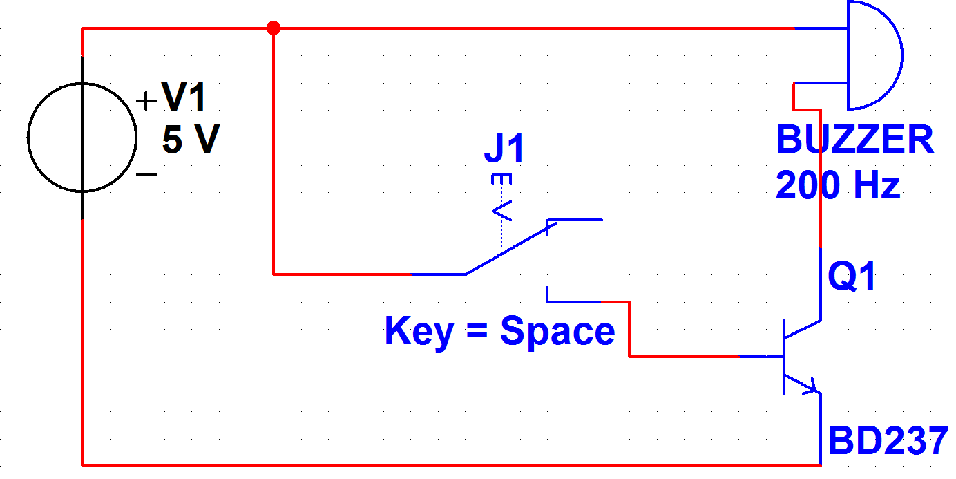
A PB-12N23PW-05Q buzzer is being used with an ATmega 162 microcontroller. Direct connection to the microcontroller pin is not feasible due to the maximum sourcing capability of 20 mA as stated in the ATmega 162 datasheet, while the buzzer...
The laser-pointer detection circuitry is capable of identifying when a laser light is directed at a specific photosensor. If the laser targets the top sensor, the comparator chip outputs a high signal. Conversely, if the laser is aimed at...