
DIY Digital Thermometer Circuit

The digital thermometer circuit is designed to provide accurate temperature readings within a specified range, utilizing a temperature sensor such as the LM35 or a thermistor, which converts temperature changes into an electrical signal. The sensor output is then fed into an analog-to-digital converter (ADC), which digitizes the analog signal for processing.
The circuit typically includes a microcontroller, such as an Arduino or PIC, which receives the digital signal from the ADC. The microcontroller processes the data and converts it into a readable format, displaying the temperature on a digital display, such as a 7-segment LED display or an LCD.
To ensure accuracy, the circuit may incorporate calibration features, allowing adjustments to account for sensor discrepancies. Power supply considerations are also crucial; the circuit can be powered by a standard battery or an external power source, with voltage regulation components included to maintain stable operation.
Additional features may include temperature logging capabilities, where the microcontroller stores temperature data over time, and an interface for connecting to a computer or smartphone for data analysis. Overall, this DIY digital thermometer circuit is a versatile project suitable for various applications, including home automation, environmental monitoring, and educational purposes.This diy digital thermometer circuit can measure temperatures up to 150?C with an accuracy of ?1?C. The temperature is read on a 1V full scale-deflectio. 🔗 External reference
Related Circuits
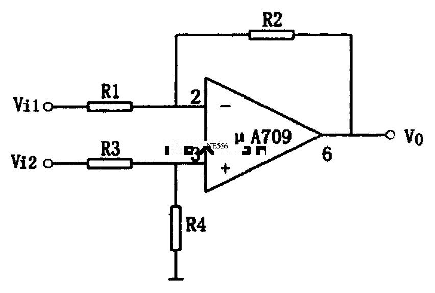
The simple differential amplifier circuit consists of two input signals, Vi1 and Vi2, which are connected through resistors R1, R3, and R4, forming a voltage divider circuit at the op-amp input. Vi1 is applied to the inverting input of...
If you are expecting an important visitor but need to step out for a moment, an electronic doorbell memory can be useful to check whether someone rang while you were away. While it cannot confirm if it was the...
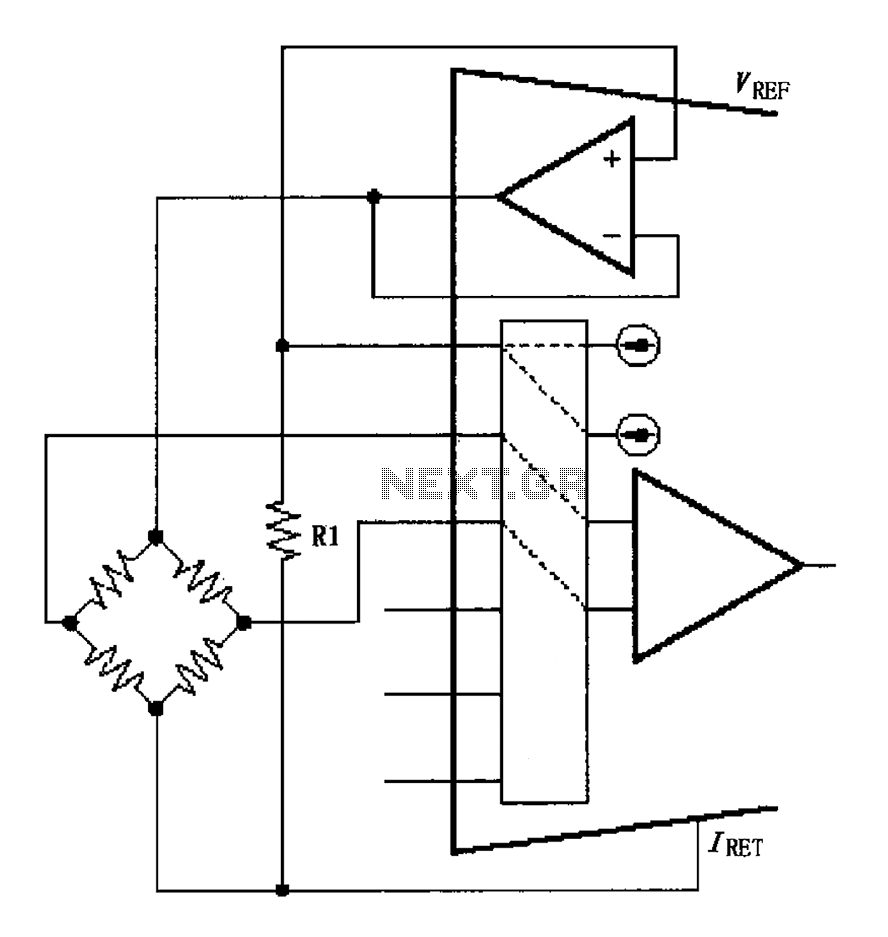
The circuit for the bridge excitation voltage XTR108 is linearized using adjusted algorithms that correspond to the linearization of the RTD response. The excitation voltage VEX is defined as 2IREFR1, where VEX represents the excitation voltage applied at both...
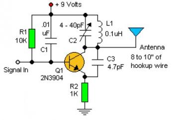
Experimenting with the size of the coil and the number of turns can influence the frequency and signal output of the oscillator. The signal can be received using a standard FM radio receiver. The input signal should be coupled...
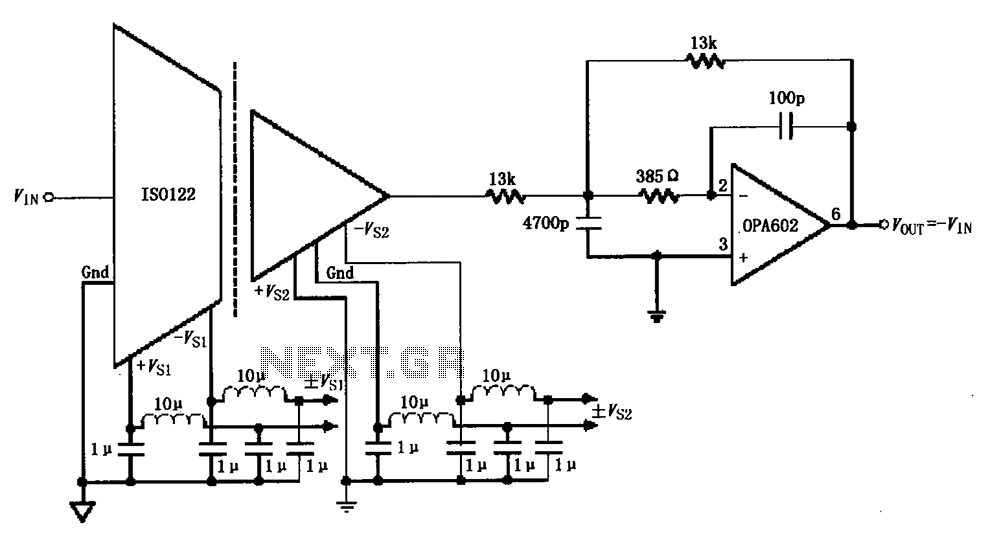
The ISO122/124-type filter circuit is designed to address noise suppression from the DC/DC converter. The internal oscillator frequency of the ISO122/124 modem is set to 500 kHz. The circuit employs inductors and capacitors for filtering to mitigate any beat...
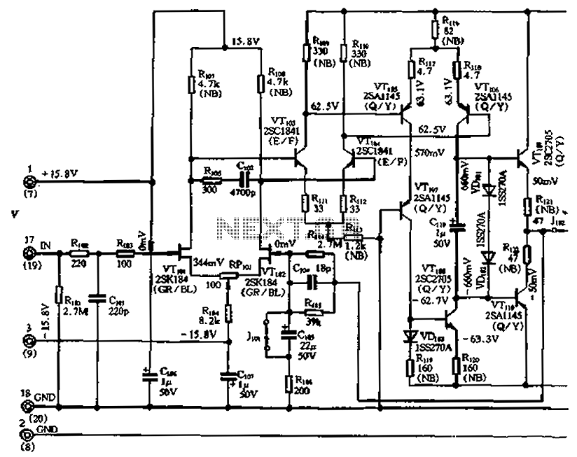
The circuit features a differential input stage that implements differential voltage amplification, forced differential voltage amplification, and a complementary push-pull amplifier output. It includes a bias circuit, a distortion servo circuit, and a protection circuit. The input preamplifier stage...