
DIY Li ion battery charger w adjustable shut off current

The Li-ion charging circuit is designed with a focus on versatility and user safety. At its core, the circuit employs a constant current/constant voltage (CC/CV) charging method, which is standard for lithium-ion batteries. The charging process begins with a constant current phase where the circuit delivers a predetermined current to the battery until the cell voltage reaches a specified threshold, typically around 4.2V. Once this voltage is reached, the circuit transitions to the constant voltage phase, where the current gradually decreases until it reaches the user-defined shut-off current.
The variable shut-off current feature is achieved through the use of an adjustable resistor or a digital potentiometer, allowing the user to set the termination current according to the specifications of the battery being charged. This flexibility is crucial for safely charging batteries of different capacities and chemistries. The circuit includes a microcontroller or an operational amplifier to monitor the cell voltage and current, providing real-time feedback and ensuring accurate termination of the charging process.
Safety features are integrated into the design to prevent overcharging and overheating. These include thermal sensors that monitor the battery temperature, as well as overvoltage protection circuits that disconnect the charger if the voltage exceeds safe limits. Additionally, the circuit can be equipped with indicators, such as LEDs, to provide visual feedback on the charging status, indicating when charging is in progress and when it has been completed.
The PCB layout is optimized for minimal interference and efficient heat dissipation, ensuring reliable performance during operation. Components are selected for their suitability in handling the currents involved, with attention paid to the ratings and tolerances of capacitors, resistors, and semiconductors used in the circuit.
Overall, this Li-ion charging circuit represents a significant advancement in DIY battery charging solutions, offering flexibility, safety, and ease of use for both amateur and experienced builders.This project started because I wanted a Li-ion charging circuit with more flexibility than afforded by other do-it-yourself circuits, but at less cost than the programmable computerized chargers. The goal from the beginning was to design, build, test and share a charger that was able to charge Li-ion cells of any size and with any number of them in parallel to a predictable and repeatable
state of charge without any trickle charging. Furthermore, the design needed to be as simple as possible; with a minimum parts count, reasonable cost, and ease of contruction to allow it to be built by an amateur (such as myself). On the advice of Silverfox, I contacted MrAl about this project, and he worked with me for months carefully considering many options and designs, all tested by him virtually on his computer, until we arrived at a design that adequately met the project goals.
I then built and tested the charger with much help from MrAl. This is the result. This charger has a unique feature among Li-ion chargers. It has a variable shut-off current to allow the user to terminate charging at a specified current level. This allows the user to not only charge cells to the desired state of charge, but also to charge many cells of the same capacity at once in parallel.
Many chargers charge cells in series, which can cause cells to become unbalanced and even overcharged. Overcharging a Li-ion cell is one of the most dangerous things you can do with one. By placing them in parallel, they are able to equalize. Note that cells with open circuit voltages differing by more than about 0. 5 Volts should NOT be connected in parallel, but should instead be charged individually. Some chargers are made to sense a certain shut off current which makes them suitable for charging cells with a certain range of capacities.
Charging larger cells results in charging to currents lower than the recommended minimum of 0. 02C to 0. 05C (depending upon your source), where C is the rated capacity. Charging smaller cells than the charger was intended for may result in charging at an unsafe rate or premature termination (don`t you hate that ). Some people prefer to terminate charging at 0. 1C in the pursuit of extended cell life. Then again, some people don`t even charge to that extent. Other folks just want every bit of capacity their cells have to offer, even if they only get a few hundred cycles out of them.
This system allows for the flexibility of charging a very wide range of individual or multiple parallel cells to the level desired. For example, an RCR123 rated at 650 mAh should be terminated at a current of about 650mA*0. 05=32. 5mA. If the charger is designed to terminate at that current, then a D sized Li-ion cell would terminate at 32.
5mA/5200mA=0. 00625. Overcharging like that would not be desirable because it prolongs the time the cell is 4. 20V - which promotes corrosion. Also, `a continuous trickle charge of over 4. 05V/cell would causes plating of metallic lithium that could lead to instabilities and compromise safety. ` source=battery university At a charge termination current of 32. 5 mA, a small sized cell such as a 10440 with a capacity 🔗 External reference
Related Circuits
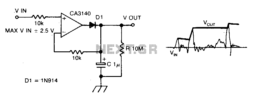
The circuit employs negative feedback exclusively for positive signals. The inverting input receives feedback only when diode D1 is forward biased, which occurs solely with positive input signals. As the positive input signal increases, the output of the operational...
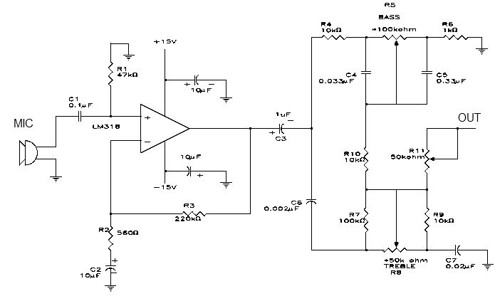
This electronic project is a simple microphone preamplifier based on the LM318 operational amplifier. The LM318 is configured as a standard non-inverting amplifier. Resistor R1 provides a ground reference for the bias current of the non-inverting input. The combination...
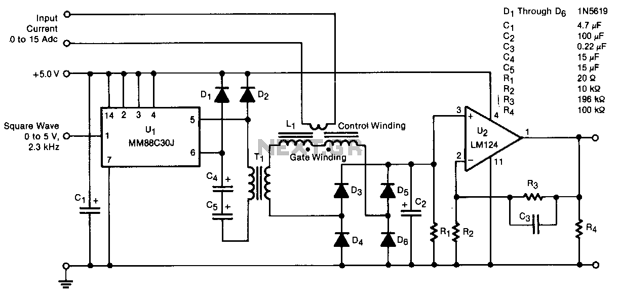
A transducer senses direct current magnetically, providing isolation between the input and the output. The detecting and isolating element is a saturable reactor, through which the input current to be measured passes via a one-turn control coil. The transducer...
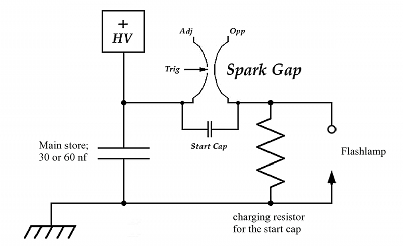
This page outlines the construction of a prototype dye laser designed for initial parameter testing. The primary objective is to determine whether a straightforward design can effectively threshold certain dyes with minimal input energy. Although the theoretical answer is...
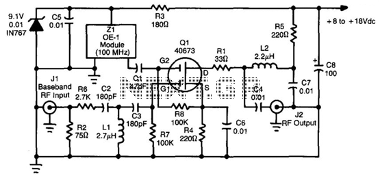
This converter utilizes a 40673 MOSFET to heterodyne the 5.5 to 8 MHz TVRO subcarriers to the FM broadcast band, enabling the use of a stereo receiver for high-fidelity stereo reception of TV sound subcarriers. Z1 is a prepackaged...
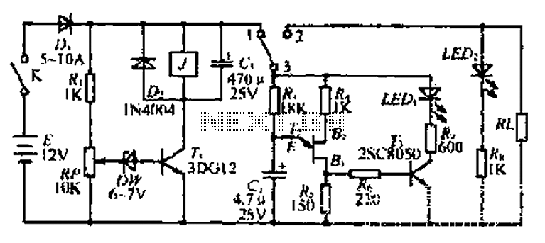
The discharge control circuit consists of a battery management system designed to prevent over-discharge of a battery. It features a relay control mechanism that activates when the battery voltage drops below a specified threshold of approximately 10.5V. The circuit...