
DIY parking sensor

To design a cost-effective parking sensor, a basic understanding of ultrasonic sensor technology is essential. The parking sensor system typically consists of an ultrasonic sensor, a microcontroller, a power supply, and an output indicator, such as a buzzer or LED.
The ultrasonic sensor emits sound waves at a frequency beyond human hearing. When these sound waves encounter an object, they reflect back to the sensor. The time taken for the sound waves to return is measured, allowing the system to calculate the distance to the object. This data is then processed by the microcontroller, which interprets the distance and triggers the output indicator based on predefined thresholds.
The microcontroller can be programmed to activate the buzzer or LED at specific distances, providing audio or visual feedback to the driver. For instance, the buzzer may sound continuously when the vehicle is within one meter of an obstacle, while an LED may flash to indicate proximity.
Power can be supplied using a battery or a DC adapter, ensuring the system is portable or can be integrated into the vehicle's electrical system. The entire assembly can be mounted discreetly on the vehicle, allowing for unobtrusive operation while enhancing safety during parking maneuvers.
In summary, a parking sensor can be constructed with minimal components and at a low cost, making it an accessible project for electronics enthusiasts.Read the article and learn how you can make your own parking sensor for just $4.99. 🔗 External reference
Related Circuits
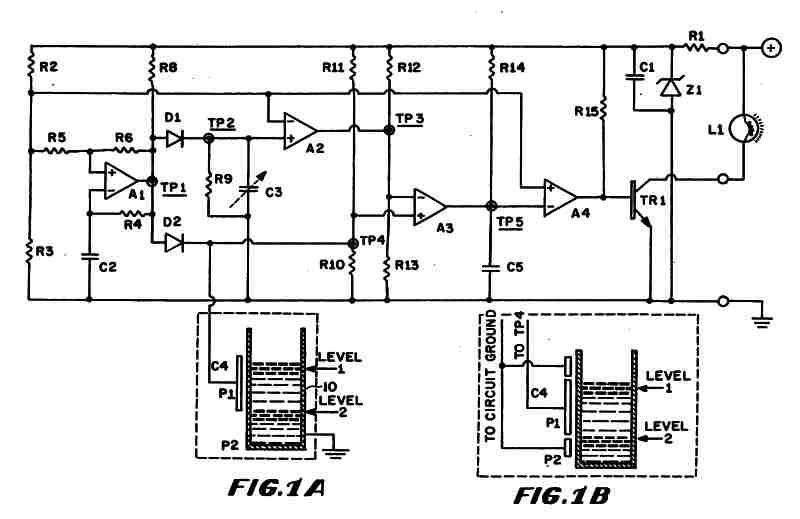
Figure 1 (A) depicts the circuit diagram of one embodiment of the fluid level detector designed. The circuit is typically powered by a 12-volt automobile battery, which is reduced to a 5-volt DC source using a voltage regulator consisting...

This liquid level sensor circuit employs a common operational amplifier IC 741 configured as a comparator. When the sensor detects that the two fluid levels (which can be represented by two small pieces of PCB or similar conductors) are...
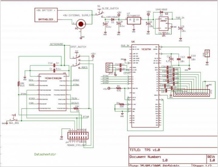
The TPA2011D1 is a 3.2-W high-efficiency, filter-free Class-D audio power amplifier housed in a 1.21 mm x 1.16 mm wafer chip scale package (WCSP) that requires only three external components. This amplifier features 95% efficiency, an 86-dB power supply...
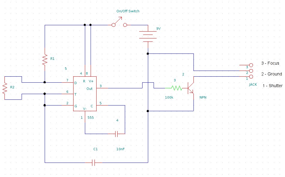
This document provides information on constructing a DIY time-lapse circuit that enables a camera to automatically capture images at specified time intervals. These images can then be compiled to create a time-lapse film. The circuit utilizes a 2.5 mm...
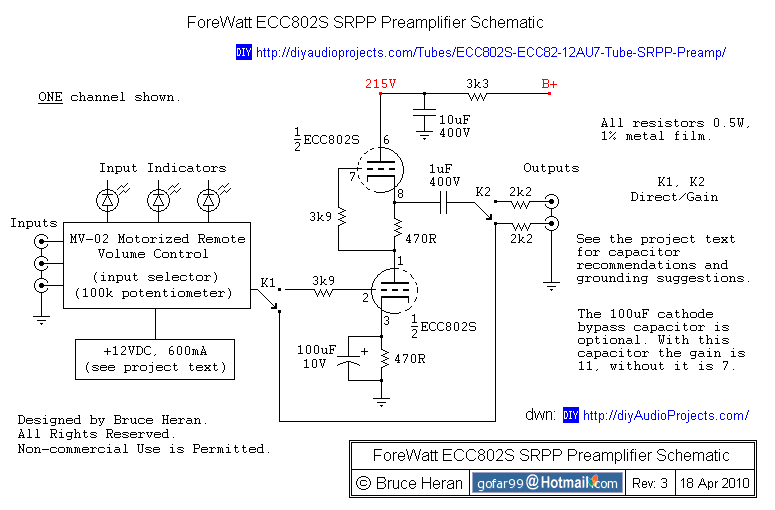
The project involves a shunt-regulated push-pull (SRPP) driver stage. Research and modeling have been conducted on the SRPP, highlighting its advantages, which include good linearity, low distortion, low output impedance, effective power supply noise rejection, and moderate gain. The...
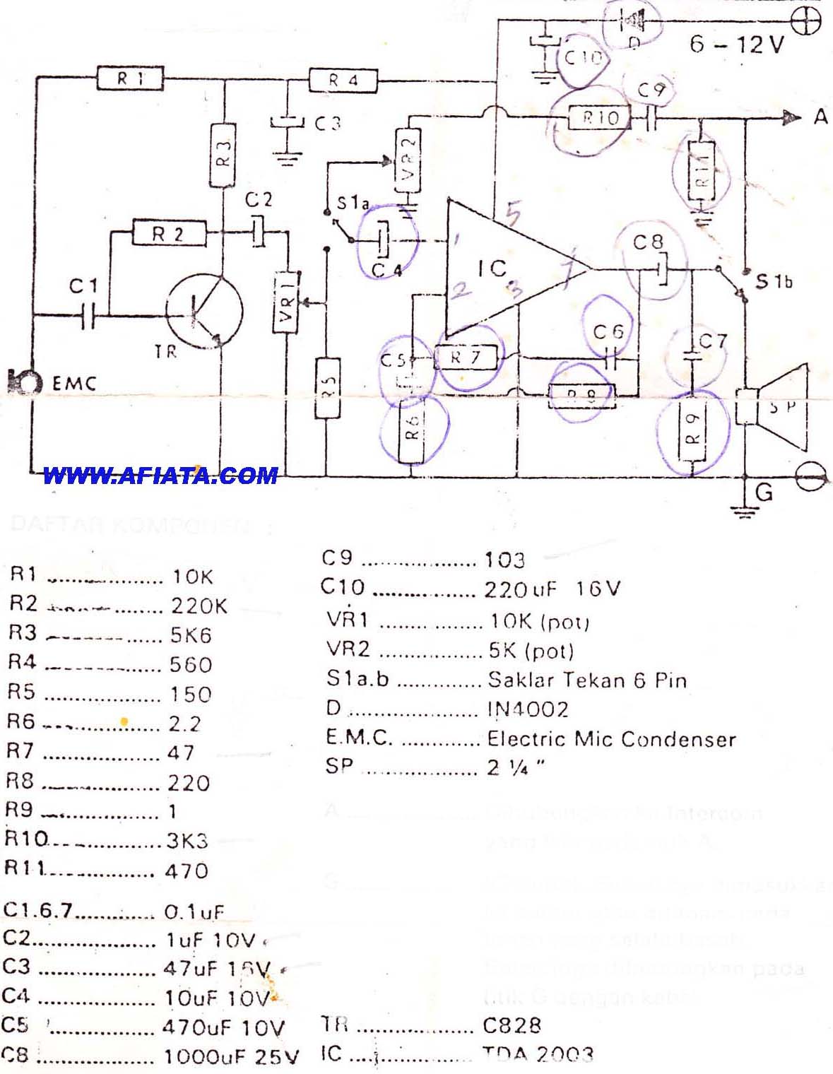
DIY Intercom Circuit Full-duplex intercom circuit schematic, cable on the way to the intercom circuit. The DIY intercom circuit is designed to facilitate two-way communication using a full-duplex system. This allows simultaneous transmission and reception of audio signals, enabling clear...