
Wireless Ir Headphone Receiver Circuit

The circuit operates by employing an IR detector diode, which is sensitive to the specified frequency of 40 kHz. This diode serves as the initial point of signal reception, converting the incoming IR light pulses into an electrical signal. The high-gain preamplifier (U1) amplifies this weak signal to a level suitable for further processing.
The amplified signal is then routed to the 4046 PLL (U2), which is configured to act as an FM detector. The PLL is adept at locking onto the frequency of the incoming signal, allowing for the extraction of the modulating audio signal. This configuration is beneficial in applications requiring the demodulation of frequency-modulated signals, such as wireless audio transmission.
Following demodulation, the audio signal is forwarded to U3, an audio amplifier. This component is responsible for boosting the audio signal to a level that can effectively drive headphones or a speaker. The choice of output device—either headphones or a speaker—depends on the application requirements, with the amplifier designed to provide sufficient power and fidelity to suit both options.
Overall, this circuit represents a compact and efficient design for receiving and processing IR signals, suitable for various audio applications, including remote control systems and wireless audio transmission systems. The integration of the IR detector, preamplifier, PLL, and audio amplifier showcases a streamlined approach to handling frequency-modulated signals. IR detector diode D1 intercepts the IR signal at around 40 kHz and feeds it from Ul, a high-gain preamp, to PLL, U2, a 4046 configured to serve as an FM detector. U3 is an audio amplifier that feeds a pair of headphones or a speaker.
Related Circuits

The tremolo circuit of the S950 is unique. The oscillator is a standard design, using half of a 12AX7. In the schematic above, the speed control is located at the lower right, the intensity control at the upper left,...
This circuit utilizes a standard loudspeaker, enabling it to function as a microphone. It allows for the use of an inexpensive loudspeaker in this capacity. Sound waves impacting the speaker cone result in variations in the voice coil. The...
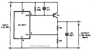
The IC8211 serves as a voltage reference and regulator amplifier, with Q1 likely functioning as the series pass transistor. R1 determines the output current of the IC8211, while C1 and C2 contribute to loop stability and help suppress the...

To ensure proper operation of the transistor in a circuit, it is essential to measure the reverse breakdown voltage of the transistor. This is particularly important for tubes with high reverse breakdown voltage requirements, such as those used in...
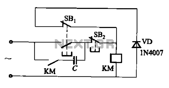
An AC contactor switch, when used with DC or pulse DC excitation, can minimize short circuit and core power consumption. This results in a significant reduction in the power consumption of the electromagnet, which can eliminate noise and reduce...
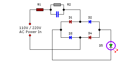
Compact yet highly functional, this is a straightforward and efficient LED circuit designed to operate directly from the AC mains supply, ranging from 100 volts to 230 volts. This LED circuit utilizes a few essential components to achieve efficient...