
Surround circuit composed by the TDA3810

The TDA3810 circuit is designed to provide high-fidelity surround sound processing, ensuring an immersive audio experience. The input coupling capacitors C1 and C2 serve to isolate the audio signals, preventing DC offsets from interfering with the audio quality. The internal buffer amplifier plays a crucial role in maintaining signal integrity by amplifying the stereo signals before they are processed.
The active phase shifter is a key component in creating the surround sound effect. By adjusting the resistance of R5, the user can fine-tune the phase shift, which alters the timing and amplitude of the audio signals sent to the main speakers. This adjustment is critical for achieving the desired spatial audio effects, allowing for a more realistic soundstage.
The electronic selector switch enables seamless transitions between surround sound and stereo modes, providing flexibility based on user preference or specific audio content. The LED indicator serves as a visual cue for the current operational mode, enhancing user interaction with the device.
Decoupling capacitors within the power supply circuit are essential for reducing noise and ensuring stable operation of the TDA3810 IC. This stability is vital for maintaining audio fidelity, especially during dynamic sound passages where sudden changes in audio levels can occur.
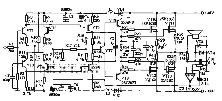
In summary, the TDA3810 circuit is an advanced solution for high-fidelity surround sound processing, integrating various components to optimize audio performance while providing user-friendly operation and adaptability. The careful design of the circuit ensures that both stereo and surround sound modes are executed with precision, making it suitable for a wide range of audio applications.Figure 1-122 is a dedicated high-fidelity surround sound processing IC TDA3810 circuit consisting of surround sound. Stereo signal via the input coupling capacitor cJ, C2 input 2,1 7 feet by the internal buffer amplifier, the left and right channel signal number sub Road. 3,16 feet all the way from the direct output signal used as the main speaker, another way to send the active phase shifter phase shift, while the left and right channels of the active phase shifters include back-channel between the two resistors R through public phase crosstalk form (L foot) and (R - L) signal crosstalk depth depends R4 (Rs) and the ratio of Rg, Rg greater the depth of the crosstalk light. Brain element R3, where, C4, q (Rs, R7 Cii, C12) with the internal operational amplifier, resistors constituting the active shift phase o phase shift by varying the extent R (R5) to adjust the resistance, resistance The larger the value, the greater the phase shift.
By reverse phase crosstalk and phase-shifted towel (L- R) and wins (R - L) signal, and then select from the switch 613 by the internal electronic circuit pin output t as a left and right channel signals deputy speaker. Electronic selector switch is used to select the circuit operation. When 11 feet when disconnect switch SA, 11 feet high, the circuit is in surround sound state. When the switch SA is closed, the pin 11 is set to 0 level, the circuit is in stereo operation, namely through state.
At this time, the stereo signal from the 2,1 7 feet after input selector switch electronically, directly from the output pin 6,13 and 3,16 feet. 7 feet of light-emitting diode VDi to display the surround sound working condition. Internal reference power supply for the IC decoupling capacitors, the internal electronics as the island selector switch t to eliminate the snubber capacitor generated when switching switching noise, cs power supply decoupling capacitors.
Resistance Rz (R6) will be part of the deputy speaker signal incorporated into the main speaker signal to form L + Card (L-R) and R + string (a foot L) signal to the main speakers o
Related Circuits
With a 1.5V battery supply, the integrated circuit LM3909 can drive the light-emitting diode NSL5027. The 300μF electrolytic capacitor acts as a timing capacitor, which limits the flash speed to approximately 1Hz. The circuit utilizes the LM3909, a popular LED...
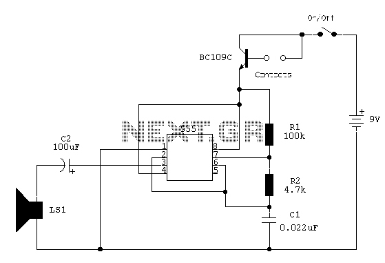
The circuit utilizes a 555 timer configured as an astable oscillator, powered by the emitter current of a BC109C transistor. In dry conditions, the transistor remains off due to the absence of bias current. However, when the probes become...
The integrated circuit LA3607 enables the configuration of a 7-band graphic equalizer for a single audio channel by incorporating additional capacitors and variable resistors. The cutoff frequency can be modified using variable resistors. It demonstrates high stability when handling...
The self-designed amplifier circuit described is completely symmetrical and complementary, effectively utilizing the advantages of complementary NPN and PNP transistors to achieve a high degree of stability. The circuit features good symmetry in the push-pull amplification state, allowing for...
This circuitry facilitates the connection between the computer's Z RS-23 serial interface and the current ring circuitry. It converts the voltage signal of the transmission into a current signal of 20 mA, achieving a maximum speed of 1200 bits....
This circuit is a simple 12V DC to 220V AC inverter that produces an AC output at line frequency, specifically 220V AC, or other voltages by selecting transformer T1. The 555 integrated circuit (IC) is configured as a low-frequency...