
USB PICKit2 programmer

The schematic in question illustrates a circuit designed around the PIC16F84 microcontroller, a popular 8-bit microcontroller from Microchip Technology. This microcontroller is capable of interfacing with various other PIC devices and can be programmed through the USB PICKit2 programmer. The schematic should incorporate the necessary connections for power supply, ground, and programming signals to facilitate communication between the PIC16F84 and the PICKit2.
In the context of using the PIC16F84, it is essential to note that this microcontroller does not contain an internal oscillator, which necessitates the addition of an external crystal oscillator. The crystal oscillator ensures that the microcontroller operates at the desired clock frequency, which is critical for accurate timing and performance. The schematic should include a crystal oscillator circuit, typically consisting of a crystal component, two load capacitors, and the appropriate connections to the oscillator pins of the PIC16F84.
Regarding the use of the F917 chip, caution is advised when experimenting with oscillator frequencies. The F917 chip features an internal oscillator, which may cause issues with the USB PICKit2 programmer if the oscillator frequency is set outside its operational specifications. Such experimentation could potentially lead to the programmer failing to recognize the chip, resulting in programming failures. It is crucial to adhere to the recommended frequency settings for the internal oscillator to avoid any adverse effects on the programming process.
When connecting the PIC16F84 to the PICKit2 programmer, the inclusion of the crystal oscillator circuit is vital to ensure proper functionality. The crystal oscillator will provide the necessary clock signal for the microcontroller to operate effectively. If the circuit is designed correctly, the PICKit2 programmer should operate without risk of damage, allowing for safe programming of the PIC16F84 microcontroller. Proper attention to these details will facilitate a robust and reliable design for development and experimentation with PIC microcontrollers.schematic of board with PIC16F84 and also other PICs which can be connected to this USB PICKit2 programmer If someone has such please show me, i`d appreciate it, thanks. another question is i heard that if i experiment with oscillator ffrequency on my demo board with F917 chip (it has internal oscillator) my USB of programmer
may be spoiled, and it wont see the chip. why is it so and if i connect another board with PIC16F84 to my PICKit2 programmer, i will also need to place CRYSTAL part there, cuz F84 has no oscillator, if i do it, my PICKit2 programmer wont be spoiled 🔗 External reference
Related Circuits
Nowadays, USB is the most popular connection between PCs and peripherals such as AVR programmers, printers, scanners, etc. For that reason, it was necessary to modify an old serial AVR In-System-Programmer (ISP) to work with a USB connection. One...
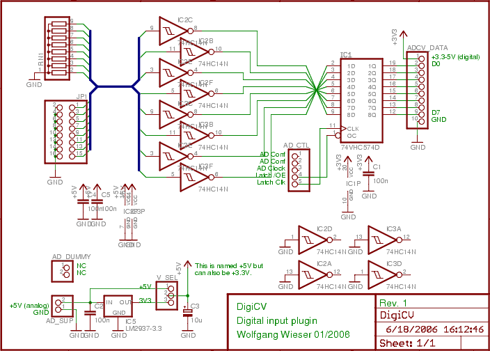
The digital input board features eight distinct digital inputs available on connector JP1. Each input is equipped with separate pull-down resistors (RN1, with a recommended value of 1 MΩ) and a Schmitt-trigger. To prevent damage from improper input voltages,...

The hardware design for USB is quite minimal, which is advantageous. However, it quickly becomes apparent that the simplicity of the hardware design leads to complex communication and control software, which will be explored further in the theory and...
An increasing number of devices operate on internal rechargeable batteries. While a compatible charger is typically included, some devices can only be charged via a USB port. This is common with USB MP3 players, which require docking with a...
During the process of organizing computer files, a schematic was discovered that was utilized in the initial phase of USB LED Matrix development. It is believed that this schematic could be beneficial to others. The schematic in question pertains to...
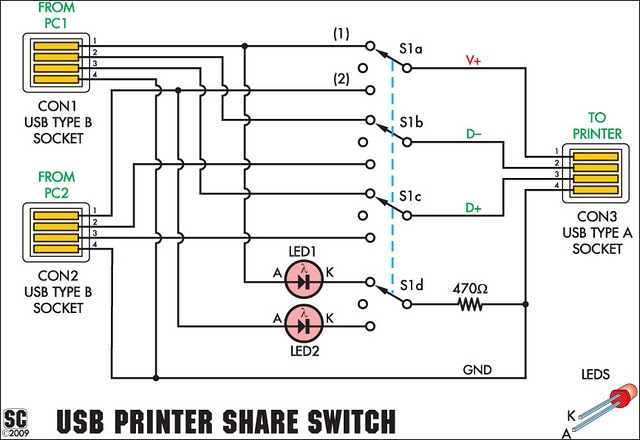
This device enables two computers to share a single USB printer or other USB devices, including external flash drives, memory card readers, or scanners. A rotary switch is used to select the PC that will access the USB device, while...