
DIY mobile phone jammer Schematic Diagram
The GSM jammer circuit operates by emitting radio frequency signals within the designated frequency range of GSM1900. The fundamental operation involves generating a noise signal that interferes with the communication between mobile phones and base stations. The circuit typically consists of several key components, including an oscillator, power amplifier, and antenna.
The oscillator generates a carrier frequency that matches the GSM1900 band frequencies. This is crucial for ensuring that the emitted signals effectively disrupt the communication of nearby mobile devices. The power amplifier boosts the signal strength to ensure it can cover a sufficient area, effectively jamming mobile phone operations within the specified range.
An antenna is used to radiate the jamming signal into the environment. The design of the antenna must be appropriate for the frequency range to maximize efficiency. Common types of antennas used in GSM jammers include dipole antennas or patch antennas, which can be designed for optimal performance in the GSM1900 frequency range.
Power supply considerations are also essential in the design of the GSM jammer. A stable and adequate power source is required to ensure the circuit operates effectively over extended periods. Additionally, it is important to consider the legal implications of using such devices, as jamming signals is prohibited in many jurisdictions.
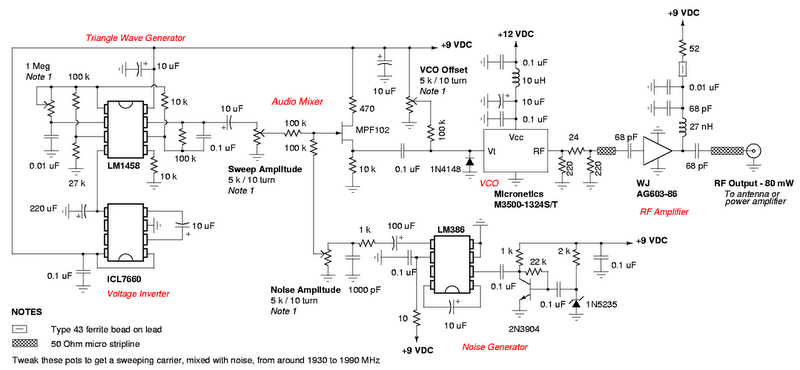
Overall, the DIY GSM jammer schematic provides a comprehensive approach to understanding how to construct a device capable of disrupting GSM1900 communications, while also highlighting the technical components and considerations involved in its design and implementation.A wonderful diy gsm jammer otherwise cellular mobile phone jammer schematic diagram instead of application single taking part in GSM1900 with frequency from 1930 MHz to 1990 MHz. The GSM1900 cellular cell phone meet people is made use of by USA, Canada and on the whole of the nations in South America.
This cellular phone jammer isn`t applicable on behalf of use in Europe, nucleus East, nor Asia. The GSM jammer circuit may well chunk transportable mobile phone signals which operates on GSM1900 group, additionally identified being DCS. You are reading the Circuits of DIY mobile phone jammer And this circuit permalink url it is 🔗 External reference
Related Circuits
A 12V switching power supply schematic has been observed to generate significant heat, which has prompted discussions among users in prominent forums, such as dp. The 12V switching power supply is a crucial component in various electronic applications, providing...
In addition to its primary function as a headphone amplifier, the circuit is suitable for various applications requiring a wide bandwidth low power amplifier. It is constructed using an operational amplifier (op-amp), with its output current enhanced by a...
This design addresses the limitations of the microphone preamp in the Sony R91, which clips at low levels, providing only 28mV of headroom for an input that may reach 1800mV, depending on the microphone and volume settings. The design...
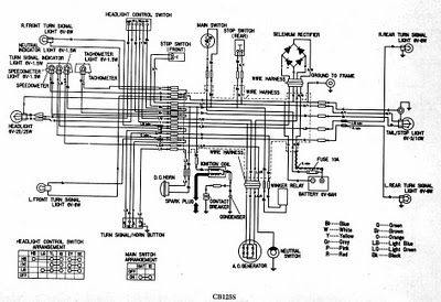
CB125S Wiring Diagram Manual PDF Download. The CB125S Wiring Diagram Manual provides a comprehensive guide for understanding the electrical system of the CB125S motorcycle. This manual includes detailed wiring diagrams that illustrate the connections between various electrical components, such as...
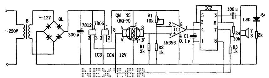
The circuit consists of a buck rectifier and voltage regulator, a gas sensor, a comparator circuit, and an alarm sound circuit. The buck regulator circuit includes a transformer, a bridge rectifier, and components such as QL, IC3 (7812), and...
This easy electronic buzzer circuit is built based on a timer that operates to generate frequency. The IC timer NE555 is used as an astable multivibrator operating at approximately 1 kHz, producing a sound when powered on. The sound...