
DMX PC Keyboard Interface circuit

The circuit design facilitates seamless communication between the PC, lighting controller, and video projector. The use of the 75176 Bus Transceiver is critical for converting DMX data, which is a standard protocol in lighting control systems. This transceiver ensures reliable data transmission over the differential bus, minimizing the risk of data corruption due to electrical noise.
The PIC microcontroller plays a vital role in this setup, particularly through its USART (Universal Synchronous Asynchronous Receiver Transmitter) capabilities. By connecting the transceiver to Pin 7 of the PIC, the system can receive DMX data effectively. The USART allows for asynchronous communication, which is particularly useful in environments where the lighting control system may need to respond to real-time inputs without delays.
Furthermore, the keyboard interface enhances user interaction with the system. The interrupt routine in the keyboard receiver is designed to monitor key presses, enabling the lighting controller to respond to user inputs instantaneously. Each key press is decoded into a specific code that the microcontroller can interpret, allowing for dynamic control of the presentation based on user commands.
Overall, this electronic schematic integrates various components to create a robust system for controlling presentations and lighting in environments where spatial separation between the PC and the lighting control is necessary. The combination of DMX data conversion, USART communication, and keyboard input handling contributes to a flexible and efficient solution for multimedia presentations.To be used with PC connected to video projectors, where the lighting controller may require control of a presentation on the video screen but the PC for the presentation is located in a different location to lighting control. The Hardware required for this project is quite simple see Circuit. The DMX data is converted inthe 75176 Bus Transceiver connecting to the USART receiver in the PIC on Pin 7.
Also in the interrupt routine in the keyboard receiver which decodes keys typed on the keyboard and the keyboard send code which send key pressed from the unit. 🔗 External reference
Related Circuits
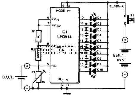
The LM3914A bar graph LED is utilized as a voltmeter for testing batteries. This circuit operates on a 4.5-V battery and compares the battery under test with an internally generated reference, established by resistors R1, R2, and potentiometer P1....
With this circuit we can change the brightness of lamb, with a only key of touch. The key of touch is connected in the circuit, center of which is a special completed IC1, which is the S566B of SIEMENS....

The LM4819 audio power amplifier is designed to amplify audio signals. An audio signal is input through the coupling capacitor (Ci) and the resistor (Ri) applied to the inverting input terminal (pin 3) of the amplifier. The inverting input...
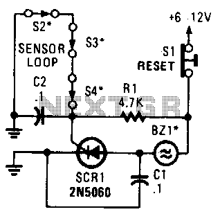
A string of three series-connected, normally closed switches is connected across the gate of a silicon-controlled rectifier (SCR). When one switch opens, the SCR is triggered through resistor R1, activating an alarm. The alarm is designed to be of...

The basic connection circuit for the ISO103 signal and power supply is illustrated. Each power supply terminal must include a bypass filter. If the isolated power supply output current exceeds 15mA, it is advisable to utilize an external filter...
The circuit below illustrates generating a single positive pulse which is delayed relative to the trigger input time. The circuit is similar to the one above but employs two stages so that both the pulse width and delay can...