
Dog Repellent Circuit

The electronic dog repellent circuit utilizes a high-frequency ultrasonic transmitter to emit sound waves that are unpleasant to dogs and cats, effectively deterring them from approaching certain areas. The core component of this circuit is typically a piezoelectric ultrasonic transducer, which converts electrical signals into ultrasonic sound waves that are inaudible to humans but can be perceived by animals.
The circuit may include a microcontroller or timer IC to control the operation of the transmitter, allowing for the adjustment of the frequency and duration of the ultrasonic pulses. A power supply, often a battery or a DC power adapter, provides the necessary voltage and current for the circuit operation. Additional components such as resistors, capacitors, and diodes may be included to filter and stabilize the output signal.
When activated, the circuit generates ultrasonic waves at a frequency often ranging from 20 kHz to 65 kHz. This frequency range is effective in repelling dogs and cats, as it falls within their hearing range but is above the threshold of human hearing. The design may also incorporate a motion sensor to trigger the ultrasonic waves only when an animal is detected, thereby conserving power and enhancing the efficiency of the device.
Overall, the electronic dog repellent circuit is a practical solution for managing unwanted animal presence in specific areas, leveraging ultrasonic technology to provide a humane deterrent.The electronic dog repellent circuit diagram below is a high output ultrasonic transmitter which is primarily intended to act as a dog and cat repeller, wh.. 🔗 External reference
Related Circuits
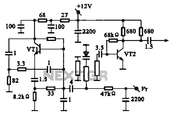
The local oscillator operates at frequencies of 1 GHz or higher, utilizing a common collector circuit, which makes it challenging to generate low-frequency self-oscillation. Typically, the local oscillator signal is passed through a buffer amplifier stage before being applied...
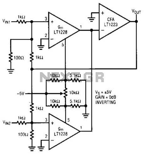
This unit captures the ATV signal by sampling the transmission line with minimal insertion loss. It features two N connectors for input and output connections, and a BNC connector is utilized for the video output. The detected output is...
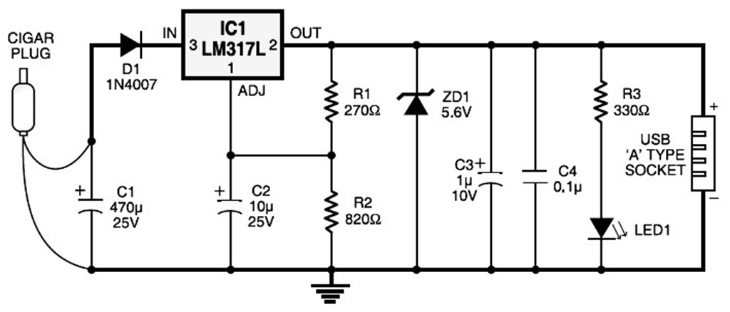
A USB port is capable of supplying more than 100 mA of continuous electric current at 5V to peripherals connected to the bus. This feature allows a USB port to power 5V DC-operated small electronic devices without issues. Many...
Switching Regulator for High Power Efficiency. When it is necessary to convert a high voltage to a significantly lower voltage, a switching regulator is the optimal choice. A switching regulator is an essential component in modern power management systems, particularly...
This circuit is designed to demonstrate high-frequency high voltage, capable of producing voltages up to approximately 30 kV, depending on the transformer used. It is economical and straightforward to construct, primarily utilizing a standard TV flyback transformer. The circuit...
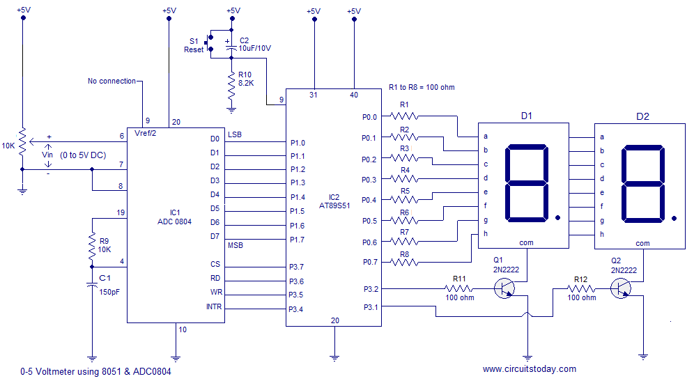
A simple 0-5 digital voltmeter utilizing the 8051 (AT89S51 microcontroller) is presented, accompanied by a circuit diagram and assembly language (ASM) code. This digital voltmeter is designed for straightforward voltage measurement. The circuit employs an AT89S51 microcontroller, which serves as...