
The equivalent circuit and a local oscillator

The local oscillator circuit is a critical component in radio frequency (RF) applications, particularly in communication systems where frequency stability and precision are paramount. The design utilizes a common collector configuration, often referred to as an emitter follower, which provides high input impedance and low output impedance. This configuration is essential for buffering the oscillator signal before it reaches the mixer, ensuring that the signal integrity is maintained while minimizing loading effects.
The buffer amplifier stage is crucial as it isolates the local oscillator from the mixer, preventing any variations in the mixer load from affecting the oscillator's frequency stability. This isolation is particularly important in high-frequency applications where even minor fluctuations can lead to significant performance degradation.
The co-collector capacitance feedback oscillator circuit is characterized by its ability to maintain oscillation through the use of feedback provided by the collector capacitance. This feedback mechanism is responsible for stabilizing the oscillation frequency and improving the overall performance of the oscillator. The use of a varactor diode in this configuration allows for electronic tuning of the oscillation frequency. The varactor's capacitance varies with the applied tuning voltage, enabling precise control over the frequency of oscillation. This tuning capability is essential for applications such as channel selection in communication systems, where different frequency channels need to be accessed dynamically.
In summary, the local oscillator circuit described is designed for high-frequency applications, employing a common collector configuration and incorporating a buffer amplifier and a co-collector capacitance feedback oscillator. The use of a varactor for tuning enhances the circuit's flexibility and functionality, making it suitable for a range of RF applications.The local oscillator at 1GHz or more to use more common collector circuit, it is not easy to produce low-frequency self-oscillation. Typically the local oscillator signal to go through a buffer amplifier stage impulse applied to the mixer, mixing action to reduce the impact on the local oscillator frequency stability. Native oscillator and the like as shown in the equivalent circuit, are co-collector capacitance feedback oscillator circuit.
When tuning voltage value changes, the capacitor connected to the oscillator circuit varactor amount of change, leading change the oscillation frequency, and thus can achieve channel selection.
Related Circuits
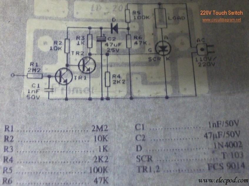
This circuit is connected directly to a 220V home electrical installation. The LOAD in the schematic diagram above represents an electronic device that consumes 220V AC current. The circuit operates by interfacing directly with the 220V AC mains supply, which...
The circuit operation begins by transmitting stereo surround sound signal quality information through the master volume circuit. This drives the left channel connected to the LCH Model TL072 IC1A and IC1B, which are linked to the right channel (Rch)....
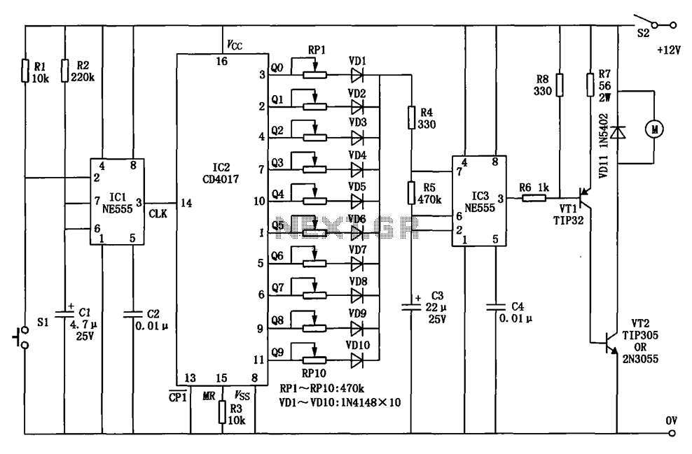
The circuit for a car wiper speed controller allows for adjustable wiper speed, ranging from one to ten cycles per second. This feature enables flexibility in operation and contributes to energy efficiency. The car wiper speed controller circuit typically employs...
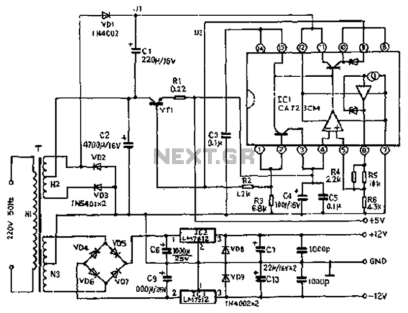
The circuit depicted features a secondary N3 center tap transformer (T) with a common point connecting diodes VD2 and VD3 to positive electrodes, along with capacitors C2, C6, C7, and negative electrodes connected to capacitors C9 and C10. Additional...
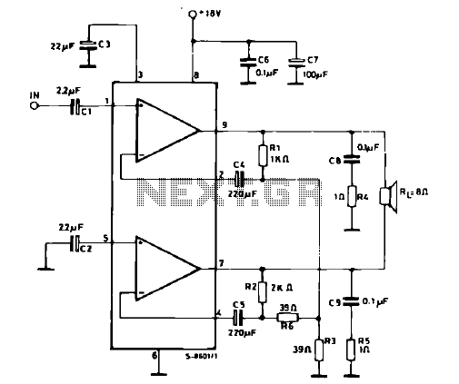
The schematic illustrates a 12 W Bridge Amplifier circuit diagram utilizing the TDA2007A, a class AB dual audio power amplifier. This amplifier is specifically designed for stereo applications in music centers, television receivers, and portable radios. As stated in...
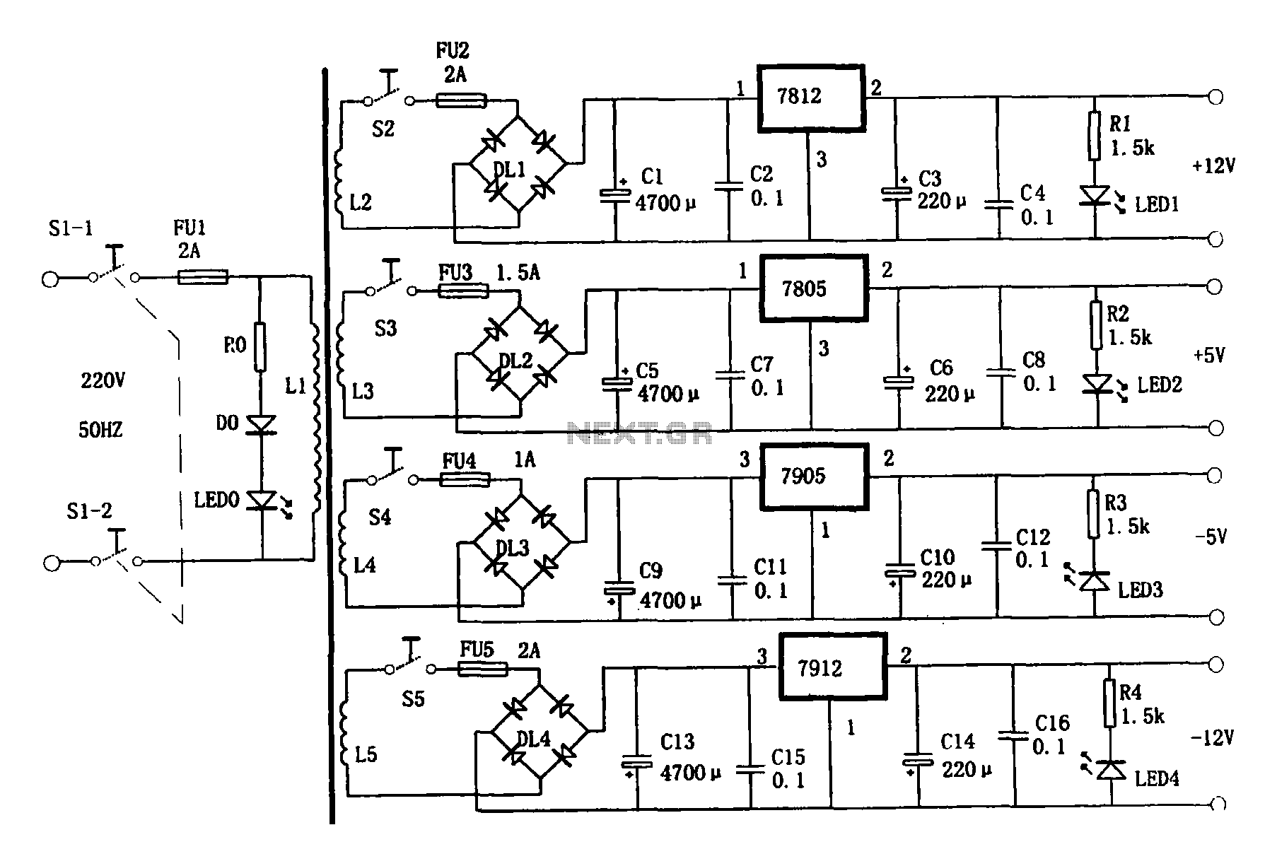
This document presents a multi-output power supply circuit. The circuit utilizes the secondary winding of a transformer and incorporates four voltage regulators: 7812, 7805, 7905, and 7912, providing independent output voltages of +12V, +5V, -5V, and -12V, respectively. Each...