
Atv Video Sampler Circuit Circuit

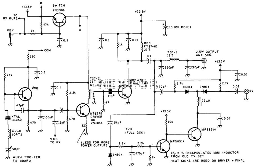
This ATV signal sampling unit is designed to provide high performance with minimal signal degradation, making it suitable for applications requiring precise video transmission. The use of N connectors ensures a robust connection, capable of handling high-frequency signals with low loss. The BNC connector for video output allows for easy integration with standard video equipment, facilitating real-time monitoring and adjustments.
The incorporation of power output meters in both models serves to inform users about the relative strength of the transmitted signal, which is crucial for maintaining optimal transmission conditions. The model with enhanced accuracy is particularly beneficial for professional applications where signal integrity is paramount.
The dual PC controls for video level and power output provide intuitive user interaction, enabling fine-tuning of the system's performance parameters. This feature is essential for achieving the desired video quality and synchronization, ensuring that the output meets the specific requirements of various broadcasting or monitoring scenarios. Overall, this unit is a vital tool for professionals in the field of ATV transmission, offering reliability and precision in signal management. This unit picks up your ATV signal by sampling the transmission line with negligible insertion loss. It uses 2 N connectors for input and output connections. A BNC connector is used on the video output. The detected output is connected to your monitor and scope so that you can accurately adjust your transmitter for proper video and synch levels.
Two different models are provided. Both have relative power output meters, but one has greater accuracy. There are two PC controls, one for video level and the other for power output.
Related Circuits
Automatic color holiday lights circuit The automatic color holiday lights circuit is designed to control the operation of decorative lights during festive seasons. This circuit typically utilizes a microcontroller or a timer to manage the sequencing and color changes...
An FM radio generates an interference signal that can be detected on another FM radio tuned 10.7 MHz higher than the original. A 50 kΩ potentiometer is used to adjust the modulation level to its maximum without introducing distortion....
This audio noise filter circuit is a bandpass filter designed for the audio frequency range. It effectively filters out unwanted signals that fall outside the audio frequencies. The circuit consists of two filters: a low-pass filter and a high-pass...
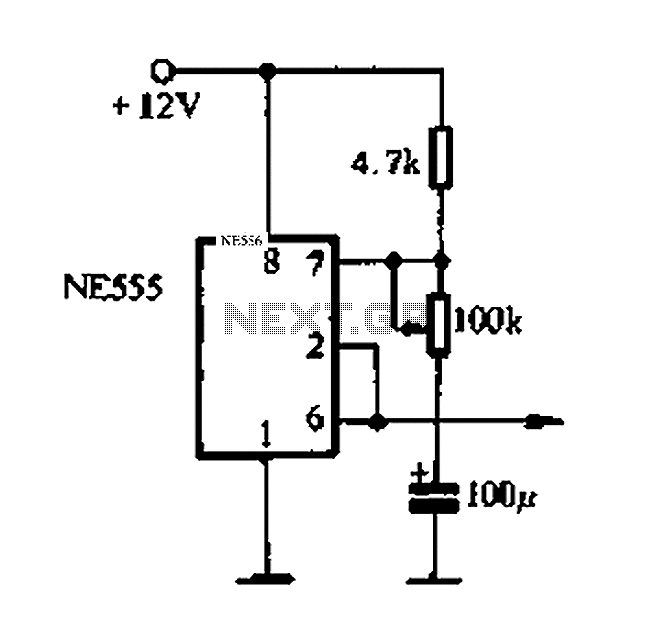
This project involves a ding-dong doorbell circuit utilizing the 555 Integrated Circuit (IC). In a previous article, a simple doorbell circuit using the UM66 IC, a CMOS three-terminal melody IC, was discussed. The current circuit employs the NE555 IC...
An advantage of a photogate over a sound trigger is that the former activates based on the exact position of the object that interrupts the beam. For instance, the shape of a snapped elastic cord can be captured as...
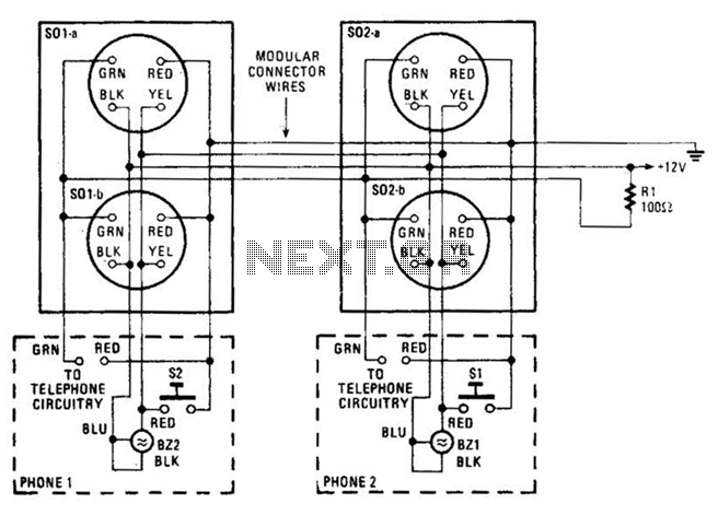
An intercom utilizing dual-modular wall jacks is depicted in this circuit. If the wires are accessible in the home telephone cable, this system can be installed with minimal difficulty. The intercom system described employs dual-modular wall jacks, which are standard...