
DOOR AJAR MONITOR

The circuit design involves a magnetic reed switch (SW1) that is mounted on the door frame, aligned with a magnet (M1) attached to the door itself. When the door is closed, the magnet holds the reed switch in a closed position, preventing current from flowing to the alarm (A1). In this state, the capacitor (C1) remains discharged, and the alarm is inactive.
When the door is opened, the magnetic field is disrupted, causing the reed switch to open. This action initiates the charging of capacitor C1 through resistor R1, which is connected in series with the switch. The time constant of the RC circuit formed by R1 and C1 determines the delay before the alarm activates. The time constant (τ) can be calculated using the formula τ = R1 × C1, where R1 is the resistance in ohms and C1 is the capacitance in farads.
After approximately 20 seconds, once the voltage across C1 reaches a threshold level, it triggers the alarm circuit, causing the beeping sound to alert individuals nearby. The alarm will continue to sound until the door is closed again, which will reset the circuit by closing the reed switch and discharging the capacitor.
This design offers a simple yet effective solution for monitoring door status and ensuring security by providing an audible alert in the event of unauthorized access. The components used in this circuit should be selected based on the required voltage and current ratings to ensure reliable operation. Additionally, the circuit can be powered using a low-voltage DC supply, making it suitable for battery-operated applications.The monitor senses an ajar door and, if the situation isn`t corrected within 20 seconds, sounds a beeping alarm. The circuit is controlled by a magnetic reed switch and magnet on the door. With the door closed, the switch is closed and the alarm is disarmed. Opening the door opens switch, C1 starts charging up through R1. Approximately 20 seconds later, th.. 🔗 External reference
Related Circuits
Figure A, B, and C illustrate the test rod end clip, with a positive power supply terminating test equipment. The B and C ends are connected in series with the load, where C represents the negative side of the...
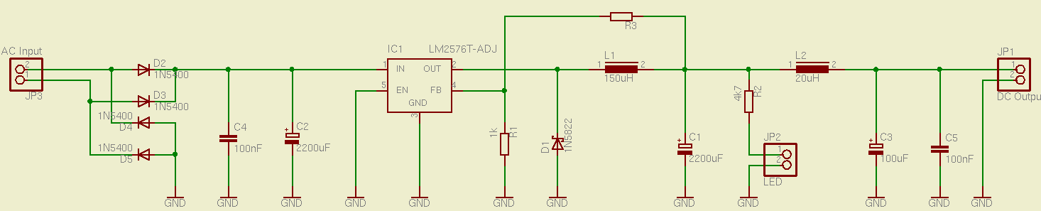
This is a simple and effective switched mode power supply (SMPS) designed to power an LCD monitor. It requires 20V at 2.3A, but the power supply unit (PSU) output voltage can be adjusted in the range of 1.2V to...
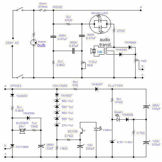
With this circuit you will be able to monitor the quality of the mains. There are 4 distinct sections, each supervising a parameter pertinent to the quality of the supply line. The noise section consists of a 50Hz filter...
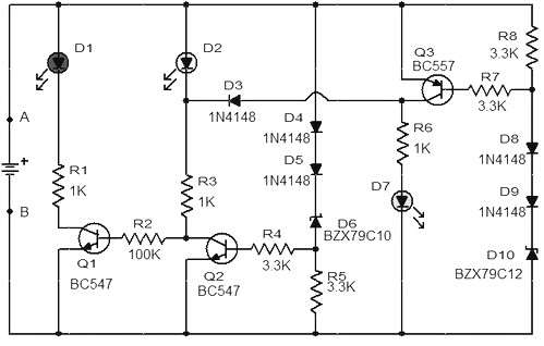
When the battery voltage is 11.5V or less, transistor Q1 is activated, and LED D1 will illuminate. When the battery voltage is between 11.5V and 13.5V, transistor Q2 is activated, causing LED D2 to light up. At a battery...

This automatic door opener can be constructed using readily available components. The electromagnetic relay at the output of this device can be utilized to control the door mechanism. The automatic door opener circuit is designed to facilitate the opening of...
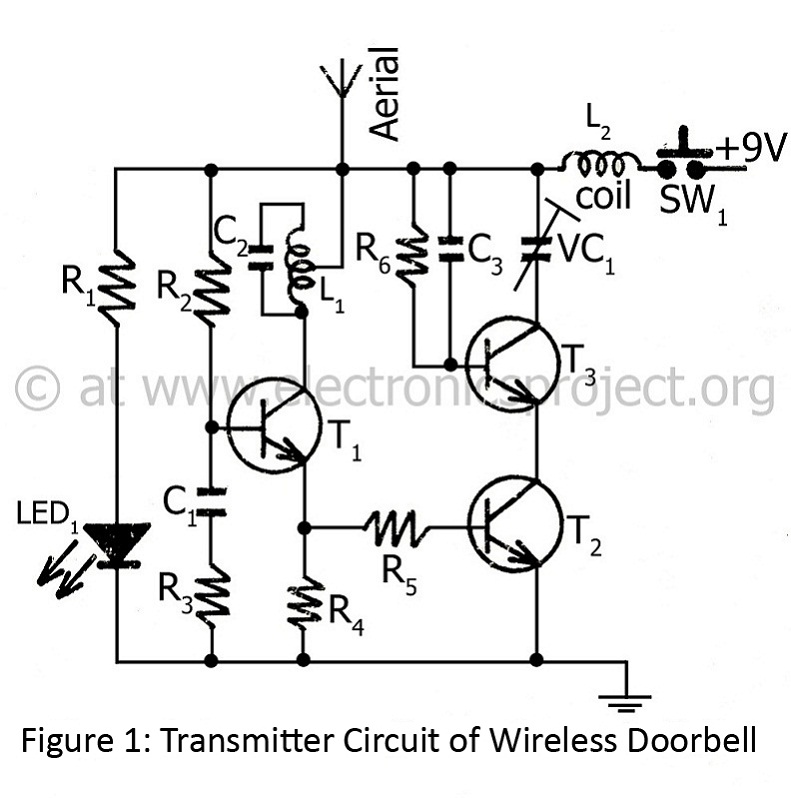
The controlling range of the wireless doorbell is 100 meters. The transmitter section is designed around an oscillator transistor (BF194B) T2, which is followed by two transistors (BC148) T1 and T3. Transistor T2 generates a specific radio frequency determined...