
Laser-Guided Door Opener

The automatic door opener circuit is designed to facilitate the opening of a door without physical contact, enhancing convenience and accessibility. The primary components of this circuit include a power supply, an electromagnetic relay, a control switch, and a sensor (such as an infrared or ultrasonic sensor) to detect the presence of an individual approaching the door.
The power supply provides the necessary voltage and current to operate the circuit. A typical configuration might use a 12V DC power supply, which is sufficient for most electromagnetic relays. The relay acts as a switch that can control higher voltage loads, such as the door motor or locking mechanism, based on the input from the control switch or sensor.
The sensor is positioned near the door to detect motion. When an individual approaches, the sensor sends a signal to the control circuit. This signal activates the electromagnetic relay, which closes the circuit and powers the door mechanism, allowing it to open. The relay is selected based on the load it needs to control; for instance, a relay rated for at least 10A at 120V AC would be suitable for most standard door motors.
In addition to the basic components, it is advisable to include a diode in parallel with the relay coil to prevent back EMF (electromotive force) when the relay is deactivated. This protection is crucial to ensure the longevity of the control circuit. A resistor-capacitor (RC) delay circuit can also be integrated to provide a delay in the operation of the door, allowing it to remain open for a predetermined time before closing automatically.
Overall, this automatic door opener circuit is an efficient solution that can be easily tailored to various door types and environments, ensuring reliable operation with minimal human intervention.This automatic door opener can be made using readily available components. The electromagnetic relay at the output of this gadget can be used to control t.. 🔗 External reference
Related Circuits
In all the houses exist the bells in the door. All want, they have the possibility of being possible to change the intensity, the tone of sound. With this circuit we have this possibility. With the materials round the...
In this doorphone circuit, an 8 ohm speaker is used both as a microphone and also an output device. The BC109C stage amplifies in common base mode, giving good voltage gain, whilst providing a low impedance input to match...
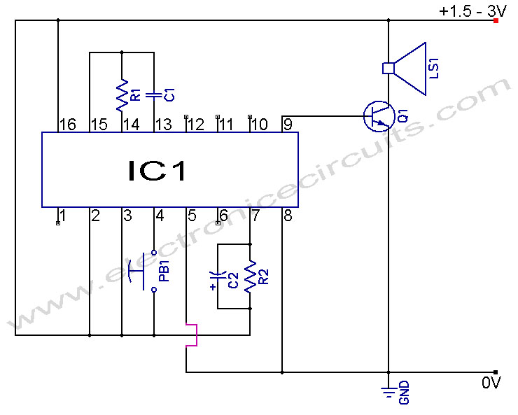
Musical Doorbell Circuit Diagram. This musical doorbell circuit utilizes the UM3481 A series integrated circuit (IC). It is designed for applications including toys and doorbells. The musical doorbell circuit leverages the capabilities of the UM3481 A series IC, which is...
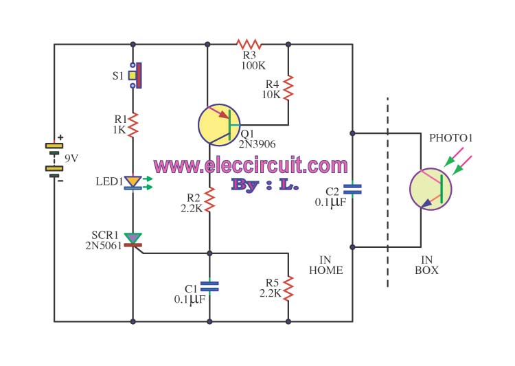
This is an integrated electronic mailbox circuit diagram designed for a front door. It activates when the door is opened. Additionally, when the cabinet photo detector is exposed to light, it will... The integrated electronic mailbox circuit is designed to...
The project described in this article is a commercially available wireless doorbell, priced at approximately $10. It is manufactured in China and is notably inexpensive, making it difficult to replicate using individual components for the same cost. This situation...
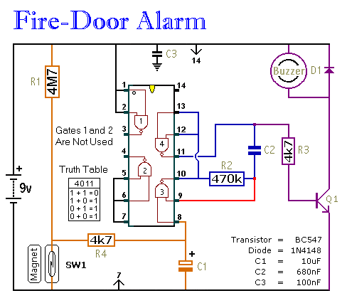
This circuit provides an alert when a door that should remain closed is left open. It is designed to be attached to a fire door, allowing normal passage. If the door remains open for more than 30 seconds, a...