
door bell circuit

The installation of the Heath/Zenith Model #LE-65-B wired doorbell involves several essential components, including a transformer, a pushbutton, and a diode, each playing a critical role in the overall functionality of the doorbell system.
The 16 Volt transformer serves as the power supply, converting standard household voltage to a lower voltage suitable for the doorbell. It is crucial that the transformer is properly rated to ensure it can deliver sufficient current to the doorbell and any additional components such as the lighted pushbutton.
The lighted pushbutton is designed to illuminate when pressed, providing a visual indication that the doorbell has been activated. This component typically consists of a momentary switch that closes the circuit when pressed, allowing current to flow from the transformer to the doorbell chime. The diode connected in the circuit serves to protect the system from potential back EMF (electromotive force) generated by the doorbell chime when it is deactivated.
In the event that the doorbell ceases to function, as described, it is important to troubleshoot the circuit systematically. Checking the transformer output voltage with a multimeter can help determine if the transformer is supplying the correct voltage. If the transformer is functioning properly, the next step would be to inspect the pushbutton for any mechanical failure or wiring issues. The diode should also be examined, as a failed diode could allow reverse voltage to damage the system.
Overall, attention to the installation and proper functioning of each component is essential to ensure the reliable operation of the wired doorbell system.Hi, Have installed a new wired doorbell. (DESA) Heath/Zenith Model #LE-65-B. (Electronic) I also changed and added a new 16 Volt Xfrmer and a lighted pushbutton and a diode. After install, all worked fine including the ""Lighted"" pushbutton. I checked the bell a few hours later, it stopped working and the pushbutton light was off.. 🔗 External reference
Related Circuits
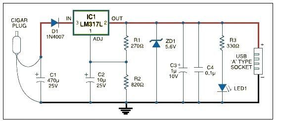
USB car charger adapter circuit design using LM317 regulator circuit The USB car charger adapter circuit utilizing the LM317 voltage regulator is designed to convert a car's 12V DC power supply into a stable 5V output, suitable for charging USB-powered...
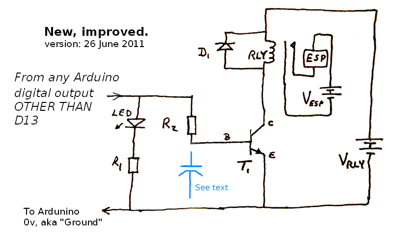
This page is browser-friendly. To enhance readability, adjust your browser window to be narrower than the full screen. The page consists of two parts: the first part features a basic program demonstrating the RFID reader's functionality, while the second...
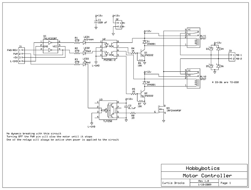
Develop a cost-effective high-current circuit that utilizes PWM. The design includes flyback diodes to protect the MOSFET from the back EMF generated by the motor when the power is switched on and off via the PWM signal. This configuration...
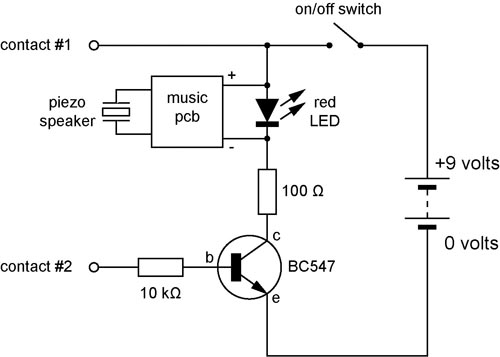
A continuity tester is useful for verifying that there is a conductive path between two points. This circuit offers the advantage of being highly sensitive, providing both visual and audible indications of continuity. An audible tester is particularly beneficial...
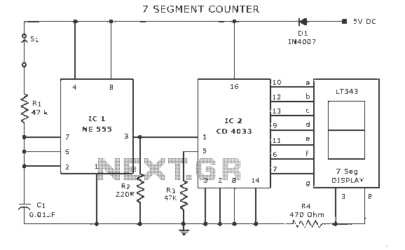
A display counter circuit is illustrated through a diagram featuring a seven-segment display controlled by the counter IC CD4033. This counter circuit is designed to visually represent incremental counts, enhancing its appeal for integration into various applications. An astable...
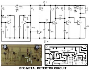
Metal Detector Circuit Overview The metal detector circuit is an electronic circuit that is specifically designed to detect metal that lies deep in the water. The metal detector circuit operates on the principle of electromagnetic induction, where a coil generates...