
Metal Detector Circuit

The metal detector circuit operates on the principle of electromagnetic induction, where a coil generates an alternating magnetic field. When metal objects enter this field, they disrupt the magnetic lines of force, inducing a secondary current in the coil. This change is detected and translated into an audible signal or visual indication, alerting the user to the presence of metal.
The circuit typically comprises a transmitter coil, a receiver coil, and associated electronic components. The transmitter coil is powered by an oscillator circuit that generates a high-frequency AC signal. This signal is then fed into the transmitter coil, creating the magnetic field. The receiver coil, positioned close to the transmitter, detects changes in the magnetic field caused by nearby metal objects.
The output from the receiver coil is processed by an amplifier circuit to enhance the signal strength. Subsequently, a demodulator converts the amplified signal into a form suitable for triggering an alarm or indicator, such as a buzzer or LED. The circuit may also include a threshold adjustment feature, allowing the user to set sensitivity levels based on the environment or the type of metal being searched.
In applications where detection is required underwater, the circuit must be waterproofed and designed to withstand harsh conditions. This may involve using specialized enclosures and materials that do not corrode or interfere with the detection process. Furthermore, the power supply for such circuits is often designed to be energy-efficient, utilizing batteries or solar cells to ensure prolonged operational life in remote areas.
Overall, the design of a metal detector circuit for underwater use combines principles of electronics, materials science, and environmental engineering to create an effective tool for locating submerged metallic objects.Metal Detector Circuit Overview The metal detector circuit is an electronic circuit that is specifically designed to detect metal that lies deep in the water. 🔗 External reference
Related Circuits
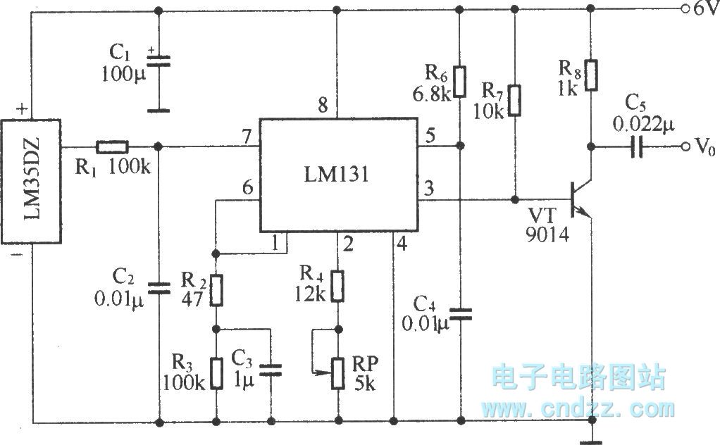
The circuit depicted in the figure integrates a temperature detection system, a temperature-voltage switch, and a voltage-frequency switch to enable remote temperature monitoring. This circuit is connected to a wireless transmission circuit, creating a remote control temperature detection system....
The game-scoring display screen circuit diagram is depicted in the image above. The circuit consists of an add/subtract scoring input circuit, an add/subtract scoring circuit, a counting-decoding display circuit, and a reset circuit. The game-scoring display circuit is designed to...

The need for a device that can detect and extinguish a fire on its own is long past due. Many house fires originate when someone is either sleeping or not home. With the invention of such a device, people...
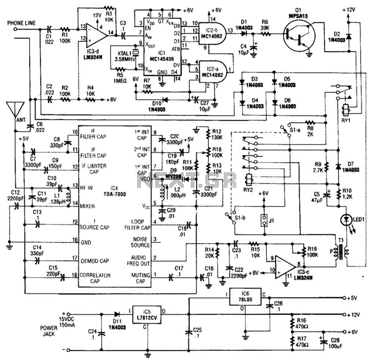
When the asterisk (*) is pressed on the touch-tone phone, a DTMF decoder, referred to as TCI, manages the on-hold logic. Audio from the FM receiver IC4 is transmitted over the telephone line when a hold condition is active....

This article presents a driver circuit for a 12V, 5W fluorescent lamp. The circuit utilizes a standard 220V to 10V step-down transformer operated in reverse to achieve a 12V output. The driver circuit for a 12V, 5W fluorescent lamp is...

To prevent the failure of electric contact pressure thermometer contacts due to singeing, it is advisable to enhance the contacts, as illustrated in Fig. 11-60. Specifically, the output termination table for DC control utilizes two two-way thyristors or a...