
Door Entry Detection for MCU Based Designs

Many may wonder why photo transistors are used instead of modulated IR receivers like the TSOP1738. The TSOP series sensors were designed for data transmission, primarily from handheld remote controls to devices such as TVs or DVD players. Specific considerations were made during the design of TSOP sensors, including maximum range to ensure ease of operation in large rooms. Due to their long range, these sensors cannot assume that only directly incident rays are reaching them; rays reflected from walls can also reach the sensor. Consequently, multiple paths exist from the Tx to Rx. This characteristic, while advantageous for TV remotes, complicates door entry detection, as obstructing one path does not necessarily prevent the IR beam from reaching the receiver via an alternate path.
Two types of IR photo transistors are available: one with a transparent white casing, which is sensitive to both IR and visible light, and another with a black casing, which is only sensitive to IR radiation. This setup will not function effectively in sunlight due to the IR component present in natural light, nor will it work in rooms illuminated by incandescent bulbs (filament bulbs). Therefore, it is advisable to use this system in environments lit by fluorescent sources, such as compact fluorescent lamps (CFLs) or tube lights.
The circuit design should include the following components: an IR LED for the transmitter, a phototransistor for the receiver, and a microcontroller for processing the output signal. The IR LED should be connected to a current-limiting resistor to prevent it from drawing excessive current. The phototransistor should be connected in a voltage divider configuration to convert the light intensity into a voltage signal that can be read by the MCU. Additional filtering capacitors may be included to stabilize the voltage output from the phototransistor, ensuring reliable operation. Proper alignment of the transmitter and receiver is crucial to maintain the integrity of the IR beam, and the mounting height should be consistent to avoid misalignment due to variations in door heights. Overall, this simple yet effective circuit design provides a foundation for various applications in occupancy detection and automated control systems.This article discuss how you can detect the entry of a person in a room and get this signal inside your MCU. This is NOT a complete project but just an idea that can be implemented in many different projects. The technique is to use use an IR transmitter and a receiver pair. One side of door will have an IR Transmitter and the other side of door w ill have an IR Receiver. The transmitter (Tx in short) will continuously send IR beam to the receiver, as long as the receiver(Rx in short) will receive this beam it will give a voltage output in range of 2. 5v to 3. 0 volts. But as this beam is obstructed, for example by someone entering the room, the receivers output will tend towards 4.
5 The IR Transmitter can be made on a small PCB as shown below. It has four mounting holes to fix it in the wall near the door. Please use 1 Watt resistor for R2 and R3 (22ohms). As you can see the optimal distance between the transmitter and receiver is 2. 0ft. to 3. 5ft. While the Rx/Tx should be mounted at the height of 3. 5ft. from the ground. Many people would ask why I have used photo transistors and not modulated IR receivers like TSOP1738 etc. The reason is that the TSOP series sensors were designed for data transfer, mainly from hand held remote control to devices like TV`s or DVD players.
So following points were kept in mind while designing TSOP sensors. Maximum range (So that remote could be easily operated in big rooms), since these have long range you cannot assume that only the rays that are directly incident on the Rx are the only rays reaching it, rays bounced from walls also reach the sensor. So actually their are more than one path from the Tx to Rx. This makes door entry detection impossible because if the person entering the room cuts one path, the ray would reach from the alternate path!
As you can see this situation is actually good for a TV remote (for which TSOPs were designed) but not for our application. Their are two types of IR Photo transistor available. One is transparent white, this one is sensitive to both IR and Visible radiations. The second one is with Black case, this one is only sensitive to IR radiation. The setup will not work in presence of sunlight due to presence of IR component in it. Nor will it work if the room is lit with incandescent bulbs (filament bulbs), so it is recommended to use this in room that is lit with florescent source like CFLs or Tube lights.
🔗 External reference
Related Circuits
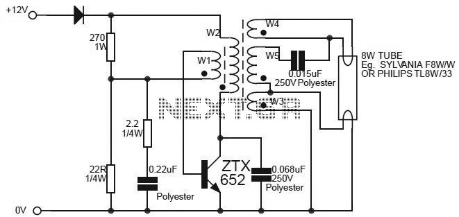
This circuit is essentially an 8W inverter circuit designed to drive an 8W fluorescent lamp from a 12V power supply. It utilizes an inexpensive inverter based on a ZTX652 transistor. The inverter will operate efficiently to convert the DC...
Figure 15-22 illustrates a doorbell system that consists of a monostable timing circuit, a password switch, a NAND gate circuit, and a sound output circuit. The operation of the circuit is designed such that when the password switch is...
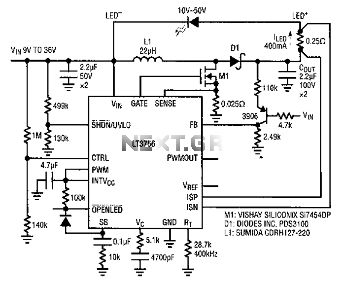
Common LED driver requirements include a wide and overlapping range of LED string voltages and input voltages. Many designers prefer to use an LED driver circuit that accommodates various battery power sources and multiple LED strings. This universal configuration...
This project gives you a fingerprint based attendance system with 8051 microcontroller. The SM630 fingerprint module is used for fingerprint matching. It can store a max of 768 fingerprints. The admin can add/delete records from the PC through the...
Eight MAX6675 integrated circuits need to be connected to a microcontroller. The clock inputs can be wired in parallel. The NCS (Chip Select) lines for pairs of MAX6675 devices (1 and 2, 3 and 4, etc.) can be connected...
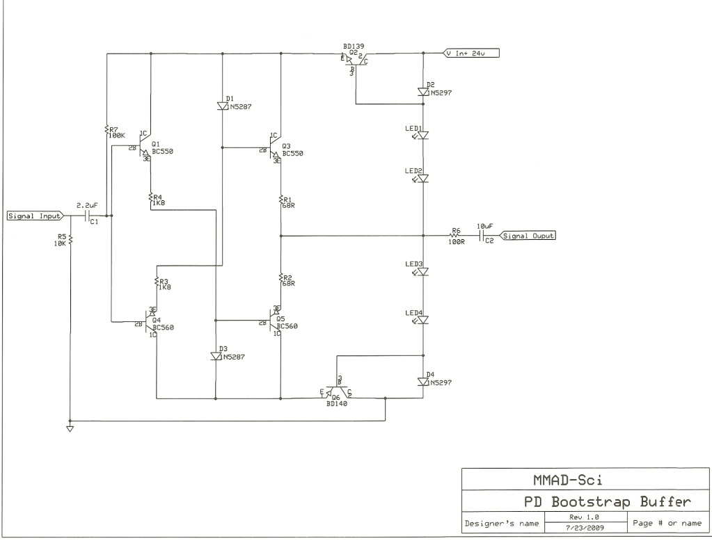
Various circuit variations have been explored, including a standalone preamp, headphone amplifier, replacements for the 321/729 circuits, and a potential active crossover, depending on demand. There has been significant interest in these designs, and the bootstrap buffer preamp is...