
Based LT3756 buck - boost mode drive circuit diagram

The described LED driver circuit operates in a buck-boost configuration, allowing it to efficiently regulate output voltage over a wide input voltage range. The design utilizes a single inductor to minimize component count, which is beneficial for reducing board space and overall system complexity. The input voltage range of 9V to 36V ensures compatibility with various power sources, including batteries of different chemistries and configurations.
The driver is capable of providing a constant output current of 400mA, which is suitable for powering LED strings with a forward voltage of 10V to 50V. This flexibility allows the driver to be used in diverse applications, from simple indicator lights to more complex lighting systems.
The inductor plays a critical role in energy transfer within the circuit. The relationship between inductor current and LED string current is crucial; as the inductor charges, it stores energy that is then released to the LED strings. The peak inductor current must be monitored, as it directly influences the peak switch current, which is necessary for ensuring that the circuit operates within safe limits.
The CTRL pin provides an analog dimming feature, which is particularly useful for applications requiring variable brightness. By adjusting the input voltage, the LED current can be reduced, thereby controlling the brightness of the LEDs. This dimming capability enhances the versatility of the driver in various lighting scenarios.
The under-voltage lockout (UVL0) feature is essential for protecting the LEDs from operating under insufficient voltage conditions. If the input voltage drops below 6V, the circuit automatically turns off the LED output, preventing potential damage to the LEDs and ensuring reliable operation.
The components COUT, D1, and MI are designed to withstand voltages up to 95V, providing an added layer of reliability and safety in the circuit. This high-voltage rating is particularly important in applications where input voltage fluctuations may occur, ensuring that the driver remains functional under varying conditions. Overall, this LED driver design represents a robust solution for a wide range of LED lighting applications, balancing efficiency, cost, and design simplicity.A common LED driver requirements are: The LED string voltage and the input voltage is very wide and overlapping. In fact, some designers prefer to use with a LED driver circuit for a variety of battery power, and a plurality of different LED strings. Such universal configuration needs to sacrifice some efficiency, component costs and board space expense, in exchange for simplicity of design time to market and product. Figure 1 is a buck-boost mode driver using a single inductor. It accepts 9V to 36V input, it is designed to 400mA of current to drive the LED strings 10V ~ 50V. Inductor current is the input current to the LED string currents; peak inductor current is equal to the peak switch current.
In the case of less than 9V input, CTRL analog dimming the LED current will be correspondingly reduced, so that the inductor current under control. UVL0 functional circuit at less than 6VIN off LED. Here, COUT, Dl and MI can withstand up to 95V.
Related Circuits
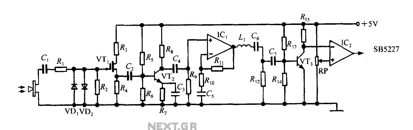
The SB5227 ultrasonic signal output is very weak and must be amplified via a power amplifier for effective transmission. A typical transmission circuit is illustrated in the accompanying figure. The SB5227 ultrasonic signal is sourced from output pin 10,...
An advantage of a photogate over a sound trigger is that the former activates based on the exact position of the object that interrupts the beam. For instance, the shape of a snapped elastic cord can be captured as...
The thermocouple cold junction compensation circuit and the MAX6675 converter circuit diagram form a temperature measuring system. The system utilizes a K-type thermocouple connected to the T terminals of the MAX6675, with the cold junction grounded. An 8051 microcontroller...
The use of programming pods has become a standard practice in manufacturing, particularly during the early development stages of firmware for new products. Once visual and structural tests are completed, the board is prepared for full functional testing. The...
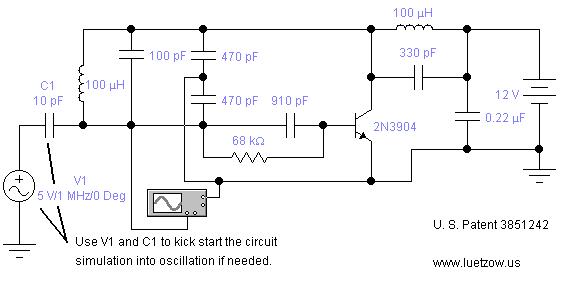
The oscillator circuits presented on this page are derived from expired or non-maintained U.S. Patents. All circuits are formatted for "Electronic Workbench 5.12" or "Multisim 7" circuit simulation software. A note regarding SPICE simulation of electronic oscillator circuits: all...
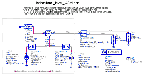
The IQ_Demod project demonstrates the application of the IQ_Demod_Setup and IQ_Demod_Data components within the ADS environment. These components are included in the ADS behavioral model suite, located under the System - Data Models palette. The file "IQ_demod_ckt.dsn" represents the...