
8W Fluorescent Lamp Inverter based ZTX652

The 8W inverter circuit is structured to facilitate the operation of a fluorescent lamp, which requires an alternating current (AC) supply to function effectively. At the core of this design is the ZTX652 transistor, which serves as a key component in the switching mechanism of the inverter. This transistor is chosen for its capability to handle sufficient current and voltage levels while providing reliable performance in the circuit.
The circuit typically includes a transformer, which is essential for stepping up the voltage from the 12V DC input to the higher voltage AC output required by the fluorescent lamp. The ZTX652 transistor operates in a switching mode, rapidly turning on and off to create a square wave output that drives the primary winding of the transformer. The secondary winding then produces the high-voltage AC needed by the lamp.
Additional components may include capacitors for filtering and stabilizing the output, resistors for biasing the transistor, and possibly a feedback mechanism to regulate the output voltage. The design emphasizes efficiency and cost-effectiveness, making it suitable for various applications where an 8W fluorescent lamp needs to be powered from a low-voltage DC source.
Safety considerations should also be taken into account, particularly regarding the high voltage generated at the output of the transformer. Proper insulation and component ratings must be adhered to in order to ensure safe operation of the inverter circuit.This circuit is basically a 8W inverter circuit. The circuit continues to be intended to drive an 8W fluorescent lamp from a 12V power supply, utilizing an cheap inverter primarily based on a ZTX652 transistor. The inverter will operate f.. 🔗 External reference
Related Circuits

An article on how to create an inverter using a simple 40-watt inverter circuit diagram and schematics. This inverter converts 12 volts to 220 volts using the CD4047 integrated circuit. The described inverter circuit utilizes the CD4047 IC, which is...

This circuit provides an intermittent siren output with an automatic reset feature. It can be operated manually through a key-switch or a hidden switch, and it can also be configured to activate automatically when the ignition is turned off....

This simple circuit can be used to flash incandescent lamps with a power rating of up to 10W. The circuit is ideal for creating flashing beacons on automobiles and similar applications. It consists of an astable multivibrator based on...

In DA3, DA5, VT1, and VT2, the first channel of the VLF Class D amplifier is assembled. The second channel is constructed using DA4, DA7, VT3, and VT4. Antiphase sine waves in the VLF range are formed at the...
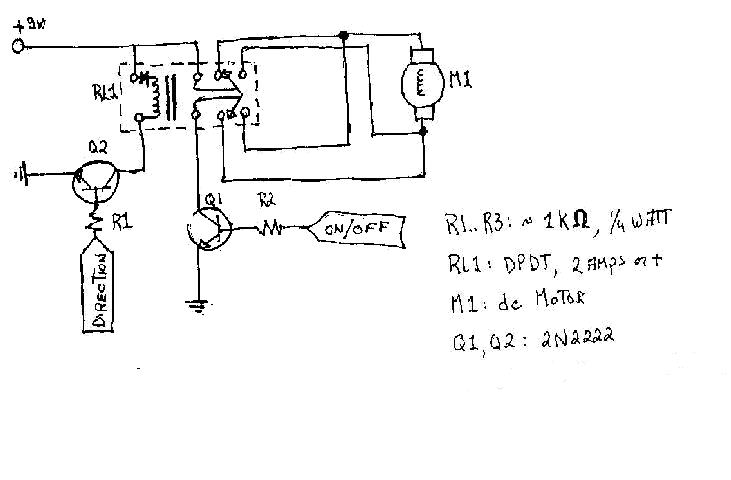
To create the circuitry described, a computer software capable of controlling a parallel port is required, with an estimated cost of approximately $30. For instance, a transistor (model number 2N2222) is priced around $0.50, while a DPDT relay costs...
The circuit is based on IC1, which is a 555 timer IC in astable mode. It will power a 6 inch 4 Watt fluorescent tube off a 12 volt supply, consuming 300 mA. It may also be powered by...