
Doorbell Warning Switch

This circuit serves as an effective solution for enhancing the visibility of a doorbell alert, particularly in environments where audio cues may be missed. The design incorporates a solenoid-type doorbell, ensuring compatibility and reliable operation. The inclusion of a series resistor, R1, is crucial; it limits the current flowing through the doorbell when the switch is engaged. The calculated voltage drop across R1 not only ensures that the transistor is activated but also minimizes power consumption, thereby prolonging the life of the power source.
The choice of resistors (22 ohms and 50 ohms in parallel) allows for a precise voltage drop that is tailored to the specific requirements of the circuit. This configuration enables the transistor to switch on effectively, allowing for the lamp to illuminate brightly when the doorbell is pressed. The electromechanical counter adds an additional layer of functionality, providing a count of the number of times the doorbell has been activated, which can be useful in monitoring visitor frequency.
Overall, this circuit design is a practical enhancement for doorbell systems, integrating visual indicators and counters while maintaining energy efficiency. Proper selection of components and careful consideration of circuit parameters are essential for achieving optimal performance and reliability.This circuit will light a lamp at a remote location when the doorbell switch is pressed. This circuit should only be used with the solenoid type doorbells, the electronic type that play tunes will not work here. It is quite easy to miss the sound of a doorbell if you are watching TV, this circuit gets round the problem by providing a visual indic
ation. As an alternative, a LED could also be used. You could just parallel a lamp across the doorbell, but this would mean extra drain from the doorbell batteries or transformer. A series resistor, R1 is wired in series with the doorbell and reduces current flow, thereby increasing battery life.
The value of R1 is chosen so that about 0. 6 to 0. 7 volts is developed across it, when the doorbell switch is pressed. I used a combination of a 22 ohm resistor in parallel with a 50 ohm. The voltage drop across R1 is sufficient to switch on the transistor, the lamp in series with the collector will then illuminate. I also used an electromechanical counter in parallel with the lamp. 🔗 External reference
Related Circuits
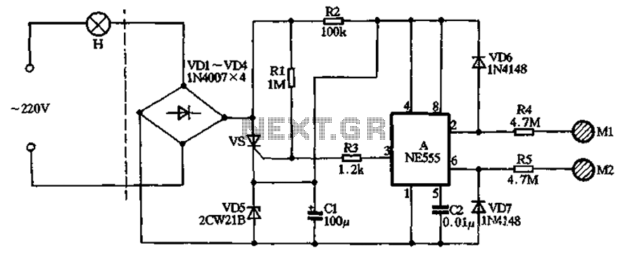
The circuit illustrated in the figure features a dashed line on the left, representing a standard lighting circuit, while the right side is responsible for the dual functionality of touch activation using the NE555 timer. Components VD1 through VD4...
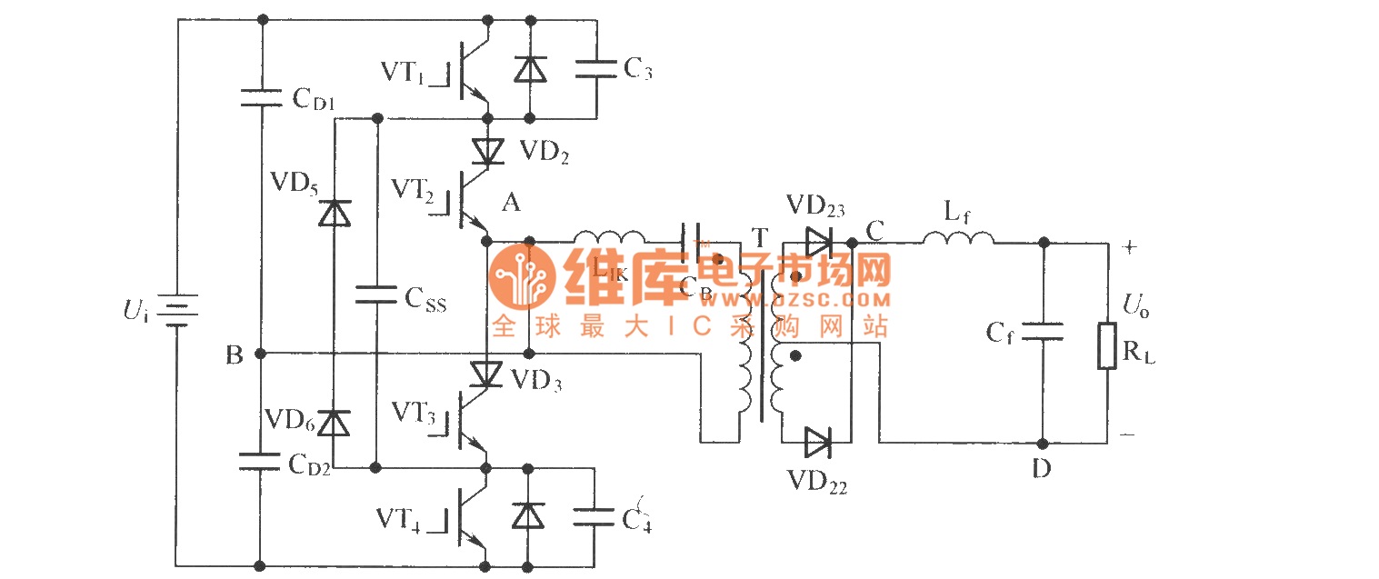
To eliminate circulating current in a zero-voltage switch three-level DC converter during its zero state, a zero-voltage zero-current switch three-level DC converter circuit has been proposed. The primary distinction between this circuit and the standard zero-voltage switch three-level DC...
A thermally controlled switch operates based on the surrounding temperature without human intervention, except during the construction of the electronic thermostat. This type of switch has numerous practical applications. For instance, it can activate an additional fan when the...

This is the primary component of the home automation system. The objective was to create a circuit board that can be customized for various functions by selectively populating the board, adding daughter boards, and modifying the software. Currently, this...

Speaker relay delay controlling circuit for audio amplifier The speaker relay delay controlling circuit is designed to manage the connection of speakers to an audio amplifier, ensuring that the speakers are activated only after a specified delay. This delay serves...
This doorbell circuit generates a low tone that transitions to a higher frequency. The total equivalent resistance connected between the base of Q1 and ground (Rbg), along with coupling capacitor C1, determines the frequency of the audio frequency (AF)...