
With NE555 make double touch light switch 2

The described circuit operates as a touch-sensitive lighting system utilizing the NE555 timer IC. The primary function of the circuit is to control the lighting based on human interaction, specifically through capacitive sensing. The bridge rectifier formed by diodes VD1 to VD4 allows for the conversion of AC voltage to DC, ensuring that the circuit can operate effectively under varying input conditions. The NE555 timer is configured in a monostable mode, where it generates a single output pulse in response to a triggering event.
The use of capacitors C1 and resistors R2 and R3 in conjunction with the rectifier diodes ensures stable voltage regulation essential for the reliable operation of the NE555 timer. The design allows for a consistent 6V output, which is critical for the timer's functionality, preventing voltage drops that could interrupt operation.
The touch sensitivity mechanism is achieved through the electrodes M1 and M2, which detect the presence of a finger through capacitive coupling. The induced noise signal is critical for triggering the timer, allowing for a responsive and user-friendly interface. The integration of rectifying diodes VD6 and VD7 ensures that the signals are appropriately conditioned for the timer's input requirements.
This circuit is well-suited for applications where touch activation is preferred, such as in lighting systems for homes, decorative installations, or interactive displays. The simplicity of the design, combined with the functionality provided by the NE555 timer, makes it an effective solution for creating touch-sensitive lighting systems. Circuit shown in Figure, the dashed line in FIG left portion as an ordinary lighting circuit, the right part of the production of the double bonds of touch with NE555 3-3 Switc hing lights. VD1 ~ VD4 form a bridge rectifier circuit, vs and VD5 constituting the main circuit switch. When vs turned on, the lights: vs when blocked, lights out. When vs in blocking state, 220V AC by VD1 ~ VD4 rectified by R2, VD5 and CI composition regulator circuit, Cl obtain about 6V DC voltage at both ends, for the time base manifold A electricity. When vs in the on -state when the alternating current through the VD1 ~ VD4 rectified by vs and VD5 constitute a loop, ends in CI can maintain 6V left and right DC voltage output.
Therefore, when the base integrated circuit DC operating voltage will not vs conduction fell. A time base circuit connected to the RS flip-flop here, when a finger touches the electrode pad Ml, human induced noise signal by R4 injection time base circuit trigger terminal 2 feet, and by the end of the trigger VD6 rectifier 2 feet to give a negative pulse trigger, time base circuit is set, the output of almost 3 feet high output power, and this time vs Rl obtained by the opening of the trigger current, light hair H powered light. Turn off the lights when needed, just fingering a lower electrode sheet M2, this time the body induced noise signal by the R5 and injected through VD7 rectified so that the time base circuit threshold terminal 6 feet to give a positive signal pulse trigger, time base circuit reset output terminal 3 pin output low, Rl positive trigger voltage is provided by the group R3 when the circuit is shorted to ground pin 3, vs loss of trigger voltage when the AC had mold that is turned off, the lamp H goes out.
Related Circuits
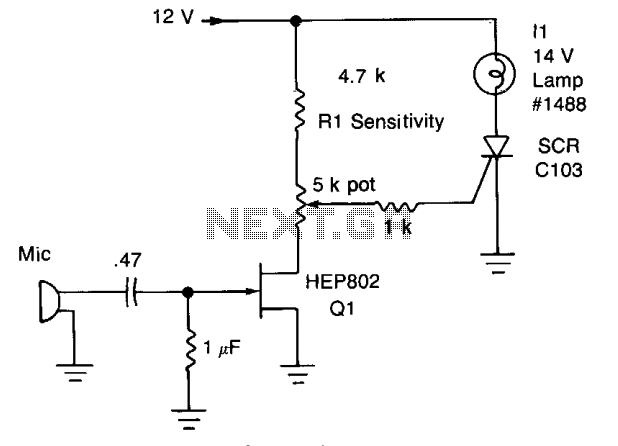
Peaks of signal (adjusted by Rl) greater than approximately 0.7 volts trigger the SCR and illuminate lamp II. The audio from the microphone is amplified by Q1. The circuit described involves a signal detection mechanism that utilizes a silicon-controlled rectifier...
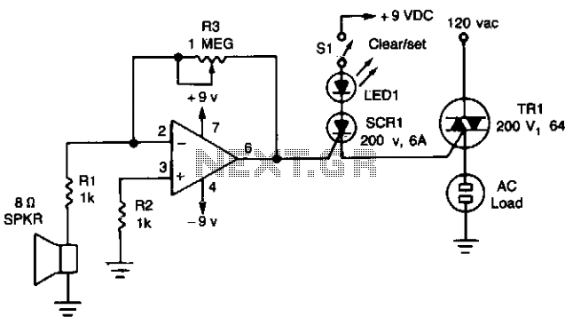
The circuit utilizes a 741 operational amplifier configured as an inverting amplifier to enhance the voltage generated by an 8-ohm speaker, which serves as a sound detection element. The feedback resistor R3, a 1-megohm potentiometer, is employed to adjust...
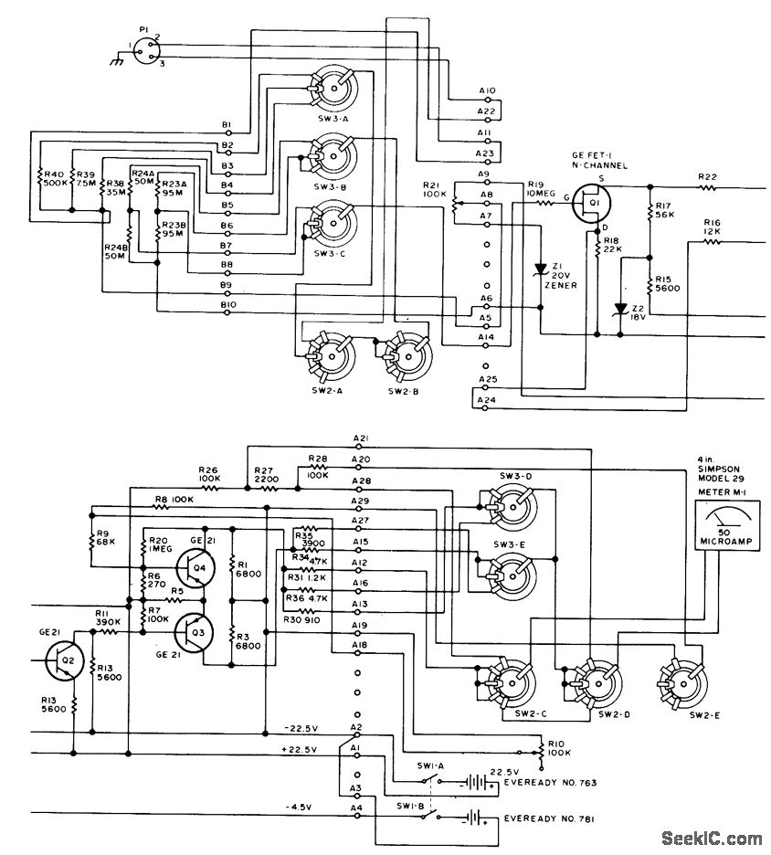
This circuit utilizes a probe that contains a Clairex 905HN light-dependent resistance element, which is connected to a DC differential amplifier. The amplifier drives a meter with a specially calibrated scale. The article outlines the calibration procedure. A switching...
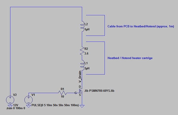
The primary concern is that the RDS_on of the utilized MOSFETs, when driven with a 5V gate voltage, is excessively low. Additionally, the reverse voltage that occurs when the MOSFET transitions from the on to the off state can...
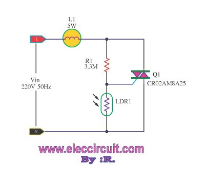
This is an automatic light dimmer circuit. There is no need to manually adjust the brightness of the lights. This circuit is highly convenient, as it utilizes a light-dependent resistor (LDR) to detect external light levels. The automatic light dimmer...
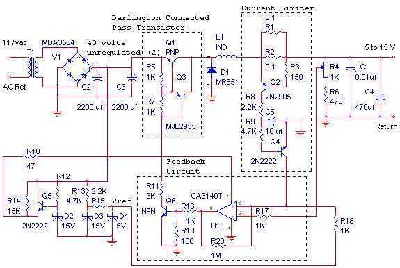
The switching power supply, shown in the schematic, provides 12 volts, at 10 amps, maximum, using a discrete transistor regulator with an op-amp functioning as a comparator in the feedback circuit. The supply was constructed in 1984 and is...