
Double-ended limit detector
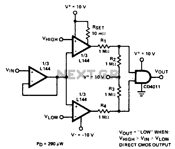
The circuit utilizes the L144 operational amplifier in conjunction with a CMOS NAND gate to effectively monitor voltage levels with minimal power consumption. The three sections of the L144 serve to amplify and process the input voltage, which fluctuates between ±10 V. This bipolar signal is transformed into a unipolar output ranging from 0 to 10 V through the use of four 1 MΩ resistors (R1, R2, R3, and R4).
These resistors are configured to create a voltage divider network that ensures the output remains within the acceptable range for the CMOS logic, which is referenced to ground. This design choice is crucial for maintaining compatibility with the digital logic levels required for subsequent processing stages.
The power dissipation characteristics of the circuit are noteworthy, with a total of 290 µW when the monitored voltage is within specified limits, indicating efficient operation under normal conditions. However, when the voltage exceeds the defined limits, the power dissipation increases to 330 µW, which may indicate a need for further analysis or additional protective measures in high-voltage scenarios.
Overall, this low-power voltage monitor circuit is suitable for applications where energy efficiency is paramount, and its design ensures reliable performance in monitoring voltage levels across a range of operational conditions.Detector uses three sections of an L144 and a CMOS NAND gate to make a very low power voltage monitor. The 1 MO resistors Rl, R2, R3, and R4 translate the bipolar ±10 V swing of the op amps to a 0 to 10 V swing acceptable to the ground-referenced CMOS logic
The total power dissipation is 290 µW while in limit and 330 /xW while out of limit. 🔗 External reference
Related Circuits
This circuit utilizes a 1458 dual operational amplifier (op-amp) to create a radar detector. Capacitor C1 serves as the radar signal detector. The first op-amp functions as a current-to-voltage converter, while the second op-amp buffers the output to drive...
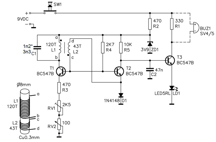
A simple home project can quickly become problematic if it encounters electric cables, gas, or water pipes, or the central heating system. Using a metal detector allows one to check for metal objects within walls, ceilings, or floors beforehand....
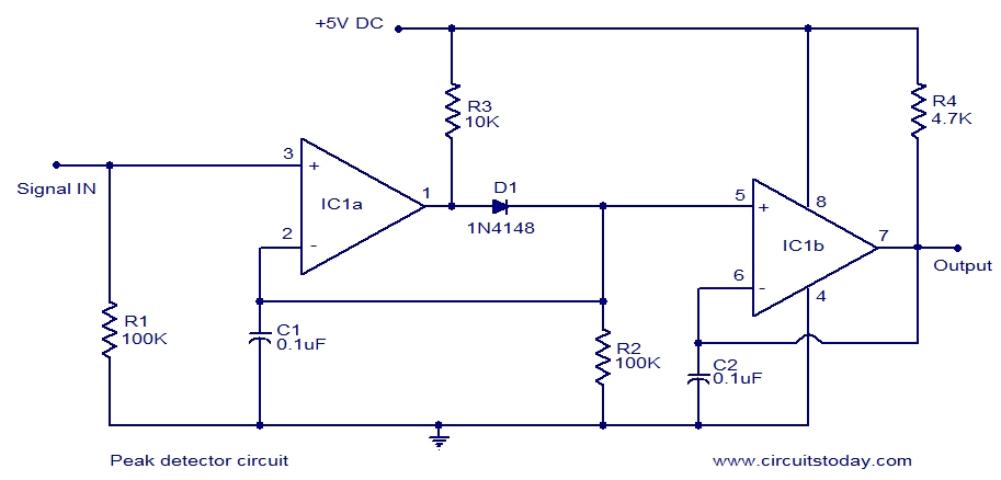
LM339-based peak detector circuit. Simple and easy to construct. Operates from a 5V DC single supply. LM339 is a dual comparator. The LM339-based peak detector circuit is designed to capture and hold the peak value of an input signal. This...
A single-chip metal detector with a detection range of a few inches. This device is useful for identifying nails or screws in walls and floors, as well as locating buried mains cables. The core of the metal detector circuit...
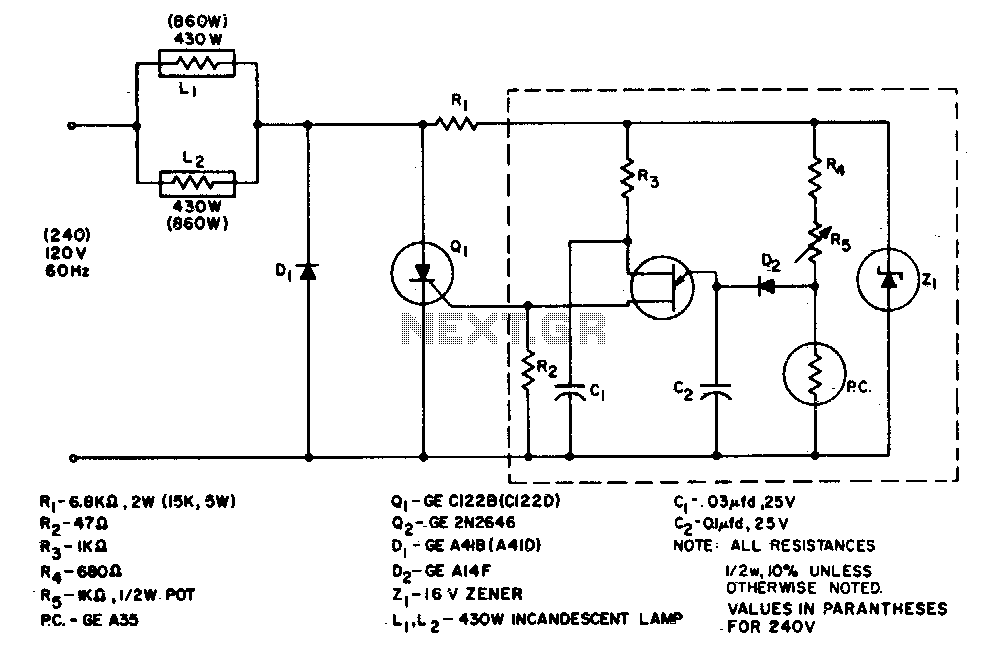
The system is designed to regulate an 860-watt lamp load from half to full power. This is achieved through the controlled half-plus-fixed half-wave phase control method. Applying half power to an incandescent lamp results in 30% of the full...
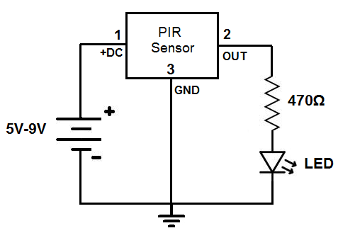
This circuit is designed to detect motion or movement, with its most common application being the detection of a person moving through an area covered by the motion detector. The primary electronic component utilized for this detection is the...