
Simple peak detector circuit using LM393. Uses minimum components and have good performance

The LM339-based peak detector circuit is designed to capture and hold the peak value of an input signal. This circuit is particularly advantageous for applications where monitoring the maximum voltage level of a fluctuating signal is necessary. The LM339 integrated circuit serves as a dual comparator, allowing it to compare the input signal against a reference voltage.
The circuit typically consists of the LM339, a capacitor, and a resistor. The input signal is fed into one of the comparator inputs, while the second input is connected to a reference voltage, which can be set using a voltage divider. When the input signal exceeds the reference voltage, the output of the comparator switches states, allowing the capacitor to charge to the peak value of the input signal.
To ensure that the peak value is held, a diode is often included in the circuit. This diode prevents the capacitor from discharging back through the comparator, thus maintaining the peak voltage until it is manually reset or until the input signal drops below a certain threshold.
The circuit operates efficiently from a single 5V DC supply, making it suitable for low-power applications. The simplicity of construction, combined with the effectiveness of the LM339 as a comparator, makes this peak detector circuit a popular choice for various electronic projects and signal processing applications.LM339 based peak detector circuit.Simple and easy to construct. Operates from 5V DC single supply. LM339 is a dual comparator.. 🔗 External reference
Related Circuits
The figure below illustrates a schematic of a highly sensitive microphone circuit designed to amplify faint sounds from a distance. The circuit exhibits significant sensitivity and offers substantial gain to weak audio signals. The microphone circuit typically consists of several...

The sound produced imitates the rise and fall of an American police siren. When first switched on, the 10 µF capacitor is discharged, and both transistors are off. When the push button switch is pressed, the 10 µF capacitor...
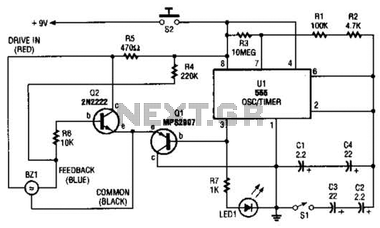
The electronic darkroom timer is constructed using a 555 oscillator/timer, a pair of general-purpose transistors, a buzzer, and an LED. The 555 timer (U1) is set up as an astable multivibrator, functioning as a free-running oscillator. The frequency of...
The most important part of this 88-108 transmitter is the Colpitts oscillator. Capacitors C3, C4, C5, C6, diodes CD1 and CD2, and inductor L1 determine the transmission frequency. The RF oscillator... The Colpitts oscillator is a type of electronic oscillator...

A series of LEDs that turn on and off in a precise sequence, creating a calming and hypnotic effect. Various LED chaser, scanner, and sequencer circuits exist, utilizing discrete transistors, logic integrated circuits (ICs), or microcontrollers. However, a common...

These are simple AVR programmers. I designed and built four different programmers for various environments: LPT controlled parallel programmer, LPT controlled ISP adapter, COM controlled ISP adapter, and COM controlled generic SPI bridge. Additionally, COM controlled adapters can be...