
Double-Sideband Suppressed-Carrier (DSB-SC) Modulator

In amplitude modulation (AM), the carrier signal's amplitude is varied in accordance with the modulating signal. This process results in the generation of sidebands that carry the information of the modulating signal. The DSB-SC technique is particularly notable as it effectively removes the carrier component, which is not necessary for the demodulation process, thereby improving power efficiency during transmission.
The modulation process can be visualized in a schematic that typically includes components such as operational amplifiers, resistors, and capacitors configured to create the desired modulation effect. The operational amplifiers serve as the primary means of manipulating the amplitude of the carrier signal based on the input from the modulating signal. The differential pairs are critical in managing the balance between the carrier and modulating signals, ensuring that the output remains clean and devoid of the carrier frequency.
The frequency analysis of the output signal can be performed using a spectrum analyzer, which will show the two sidebands and confirm the absence of the carrier frequency. This capability allows for efficient use of bandwidth and power in communication systems, making DSB-SC modulation a preferred choice in various applications, including broadcast radio and data transmission. The careful design of the circuit components and their configurations is essential for achieving the desired modulation characteristics while maintaining signal integrity.When we modulate a carrier signal with amplitude modulation, there will be four frequency components as the result. The first is the modulating signal itself, the second is the frequency carrier, the the latest two are the difference and the sum of the carrier and the modulating signal.
The spectrum of these frequencies can be seen using frequenc y analyzer. In radio transmission, the modulating frequency components is completely filtered out since the frequency is far lower than the other three. To increase the power efficiency, double sideband suppressed carrier modulator (DSB-SC) remove the carrier frequency part, so the transmitted frequencies consist only the side bands: the sum and the difference.
In the schematic diagram below, a double-sideband suppressed-carrier modulator circuit is presented. There is no carrier appear in the output because of the basic current. The Carrier amount appear in at the output can be controlled by adding offsets to the carrier differential pairs. The function of the modulation signal-AM modulation is the amplitude. 🔗 External reference
Related Circuits
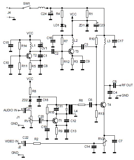
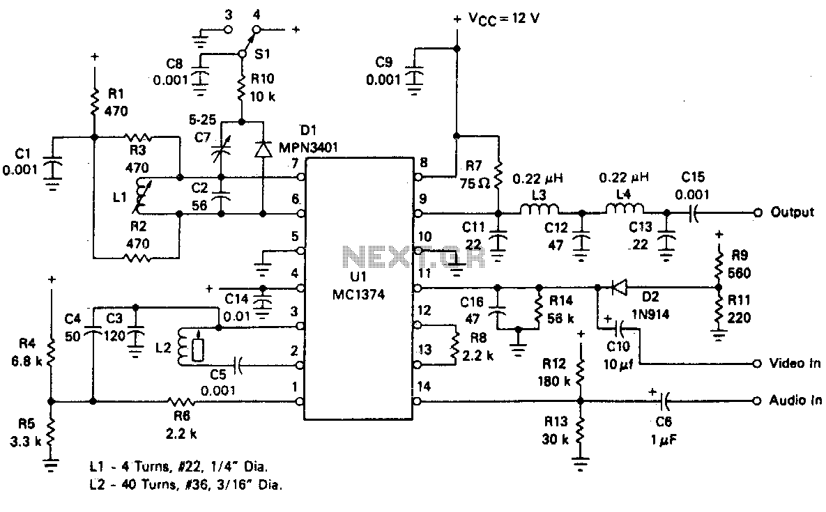
The circuit converts audio and video signals into a UHF TV signal, allowing a video signal from a camera or other source to be connected to a standard TV set. The audio and video signals are transformed into a...
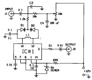
The FM modulator circuit, which utilizes frequency modulation, is constructed with a Motorola MC1648P oscillator. It employs two varactors, specifically Motorola MV-209, to achieve frequency modulation of the oscillator. A 5000 Ω potentiometer is incorporated to bias the varactors...
More: An electronic schematic is a representation of the components and connections within an electronic circuit. It serves as a blueprint for constructing electronic devices, allowing engineers and technicians to visualize how components interact and function together. The schematic...
The circuit is an amplifier with bias at cutoff. Transistor Q5 functions similarly to a grid-leak detector. In the absence of a subcarrier input, the demodulator is disabled, preventing any signals from passing through. It is essential for the...
The FM oscillator/modulator is a voltage-controlled oscillator that demonstrates a nearly linear relationship between output frequency and input voltage across a broad frequency deviation. It serves as an effective FM source with minimal additional components required. The device operates...
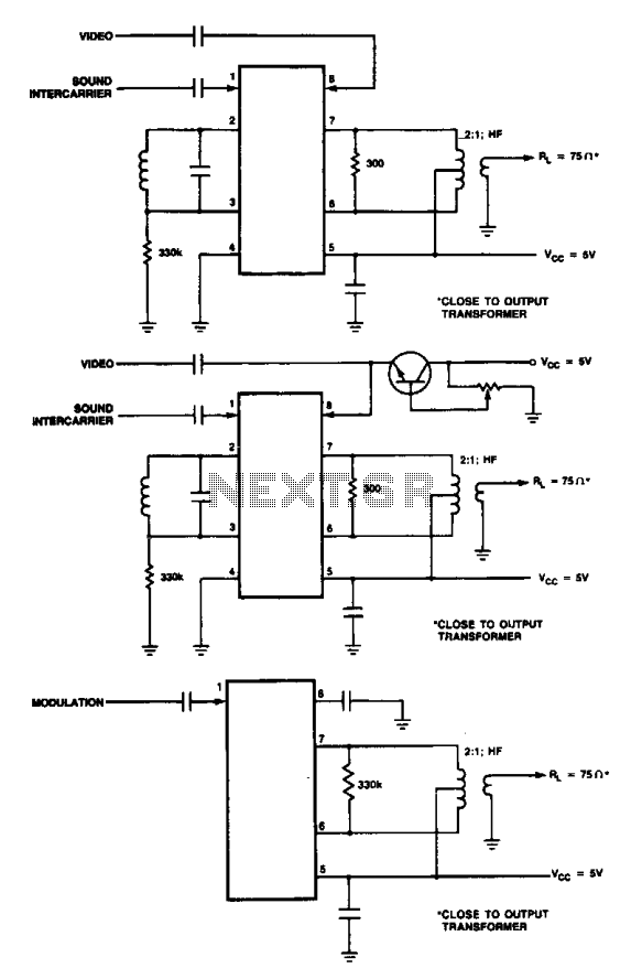
These are modulator circuits designed for the modulation of video signals on a VHF/UHF carrier. The circuits require a 5 V power supply and a few external components for negative modulation mode. For positive modulation, an external clamp circuit...