
Drinking driver detection circuit

The circuit operates on the principle of alcohol detection using a resistive sensor, which alters its resistance in the presence of alcohol vapors. When the sensor detects alcohol, the corresponding change in voltage at point B is processed by the LM358 comparator, which serves as a threshold detector. The circuit is designed to provide immediate feedback to the driver through visual (LED indicators) and auditory (voice prompts) means.
The LED indicators serve dual purposes: LED2 (red) indicates the presence of alcohol and prompts the driver to stop, while LED3 (green) signals a safe driving condition. This dual feedback mechanism enhances driver awareness and safety. The adjustable sensitivity potentiometer (RP) allows for fine-tuning of the circuit to different environmental conditions and sensor calibration.
The inclusion of a manual switch (S2) allows the user to disable the system temporarily, which is crucial for testing or maintenance purposes, preventing unintentional alerts during non-driving scenarios. The timing components associated with the voice circuit are critical for generating appropriate sound frequencies, which can be adjusted to ensure clarity and audibility in various environments.
The overall design emphasizes safety by integrating multiple feedback mechanisms and ensuring that the alcohol sensor operates reliably under varying conditions. The circuit effectively combines electronic components to create a comprehensive system aimed at reducing the risks associated with drinking and driving. Car drivers, motorcyclists despite prohibit drinking and driving, but also have occurred, in this case the circuit can be detected the odor of alcohol when. Issued a do not dri nk and drive the voice prompts sound immediately. When not detected the odor of alcohol, I wish you a safe journey home, the voice is raised. To warn drivers not to drink and drive, with a reminder. (1) to Tuen Mun Road and the principle of the circuit components shown in FIG 6H44. QM-NJ9 circuit is alcohol sensor. QM-NJ9 exposed to alcohol after the ignorant, the resistance value of A, B between the reduction potential of the point B rises, the more concentrated alcohol, the higher the B point potential. This signal voltage by a sensitivity adjustment potentiometer RP, sliding arm removed and added to the LM358 dual voltage comparator, feet, and the comparator, pin voltage reference by the crown, R sub- pressure decision that, feet the potential of the product is fixed at V-Vcc/(R3 + R4) a 1.47V.
The two LM358 comparator input is connected to the anti- pick. According to the voltage comparator principle known: If, pin signal voltage is less than 1. 47V voltage, feet set, the comparator O pin output low, LED2 off, off. While the lower comparator output high Royal basis. LED3 (green) positive bias, light, and touch the hair of voice circuits TP-1106K Wei Ying foot end, the speaker issued a Y I wish you a safe journey home, said the driver to be wine. If, pin signal voltage is higher than 1. 47V, the next comparator pin output low, LED3 off, off. The comparator O pin output high, LEDZ (red) light, and trigger TI - 1106K feet TGl the end, the speaker BL issued a do not drink and drive, the warning that the drivers alcohol consumption exceeds the standard, should be mandatory stop driving.
Island is QM-I.U9 filament FF current limiting resistor, both ends of the filament heating voltage stability (5 persons o- z) v, it will ensure that alcohol sensor with high sensitivity and stability work. Because alcohol sensors before work need to preheat 5-lOmin. Wait until the stability can be detected, and any time there is a two comparator output high, in order to prevent false triggering language tone circuit, so set up a manual switch S2.
Just then detected at S2, immediately you can let go. VD1, VD2 buck diode tube. TP-1106K in order to ensure the right fit supply voltage (2.5 ~ 4.5V). Timing components hurricane, C adjustable voice circuits operating frequency, thus changing the sound tone.
Related Circuits
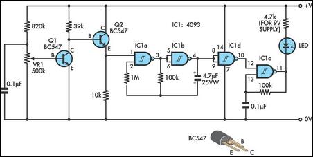
The homemade wireless remote control circuit diagram illustrates a motor remote control transmitter circuit. The circuit utilizes a 555 timer along with resistors R1, R2, RP1, diodes VD1, VD2, and capacitor C1 to create a variable duty cycle astable...
This circuit utilizes two quad op-amps to create an eight LED audio level meter. The op-amp employed in this circuit is the LM324, a widely used integrated circuit that is readily available from numerous electronic component suppliers. The 1K...
If the offset value exceeds 5mV, adjust this value by experimenting with resistors, starting with 220K, connected from test point Z (the junction of R22 and R23) to +V if there is a negative voltage, or to -V if...
This design integrates power-on and low-battery indications, capable of operating with any battery voltage up to 15V. It features a very low current drain of 2mA or less and costs less than $3.50 with new components. When the battery...
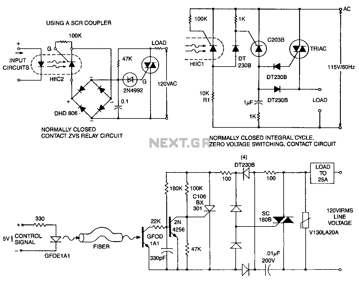
This circuit is effective for lamp and heater loads. Some circuits driving reactive loads require integral cycling and zero-voltage switching when an identical number of positive and negative half-cycles of voltage are applied to the load during a power...
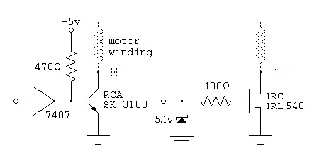
To control a stepper motor, each winding must be energized individually in a specific and timed sequence. This energization is carried out by a driver circuit, which acts as an amplifier. The timing is managed by an indexer circuit,...