
Constant Voltage Speaker Measurement Circuit

In this circuit, the goal is to calibrate an analog measurement system that converts resistance values into a corresponding voltage output. The calibration process begins by addressing any offset voltage that may be present, which is critical for accurate readings. The use of a resistor in the range of 220K provides a means to fine-tune the offset, ensuring the system can achieve a zero voltage reading at the calibration point (Cal).
The choice of a 100K potentiometer allows for flexible adjustments, providing a user-friendly interface for calibration. By connecting a voltmeter to the output and adjusting potentiometer P1, the output voltage can be set to correspond to the measured resistance multiplied by a scaling factor of 10mV. This scaling factor is essential for translating the resistance value into a usable voltage output, which is particularly important when dealing with low resistance values such as 8.2 ohms.
To confirm the accuracy and linearity of the system, the original resistor can be replaced with a known 120-ohm resistor. This step is crucial as it tests the system's response across a different resistance value, ensuring that the output remains proportional to the resistance input. The expected output voltage should align closely with the calculated value of 10mV multiplied by the resistance, providing a clear indication of the system's performance.
If discrepancies arise in the output voltage, adjusting R6 becomes necessary. This resistor plays a pivotal role in the final output calibration, and its value can be lowered to correct any significant deviations. The option to use a trimpot for R6 allows for precise adjustments, facilitating fine-tuning of the output voltage.
Finally, the importance of performing level and output calibration steps cannot be overstated. These steps are essential for maintaining the integrity of measurements, particularly when the system is used for different sets of measurements. Allowing the readings to stabilize before altering the frequency ensures the accuracy of the output, thereby enhancing the reliability of the entire measurement system.If there are more than some 5mV, reduce this offset value by experimenting with resistors (220K a good starting point) from testpoint Z (junction of R22/R23) to +v if there is a negative voltage or to -v if there is a positive voltage until the voltage at Cal is as close to zero as you care to go (I did it this way to save a trimpot - you can opt to place a 100K pot between +v and -v and a 100K resistor at the slide and have a nice, easy adjustment). Place the voltmeter at the output and adjust P1 until the reading is (the value you measured for the 8. 2 ohms resistor) times 10mV (say you measured 8. 4 ohms - adjust for 84mV) Check linearity by replacing the 8. 2 ohms resistor by a 120 ohms one (measure it`s value, also). The output voltage shall be very close to 10mV times the real value, circa 1. 2V. If the voltage is grossly out, you need to adjust R6 (again, if you prefer it can be a trimpot) by lowering its value until suddenly there will be the correct value at Out.
Do not forget to do the level calibration ( step 3-g ) and output ( step 3-h ) every time you start a new set of measurements and wait for the reading to stabilize before changing frequency. 🔗 External reference
Related Circuits

The circuit comprises four main components: a binary counter, a digital-to-analog (D/A) converter, a voltage-controlled oscillator (VCO), and an audio output amplifier. The counting speed of the binary counter is influenced by the frequency output from the VCO, which...
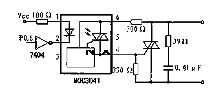
A dimming control circuit is implemented using a single-chip I/O port sinking method to control a thyristor switch for dimming functionality. The MOC3041 optocoupler features an internal zero-crossing detection circuit, allowing for effective control of the thyristor. This design...
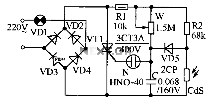
This circuit is designed to automatically adjust the brightness of lights based on the ambient light intensity. In bright conditions, the lights remain off, while in low ambient brightness, the lights are activated. The circuit incorporates a thyristor (VT1)...
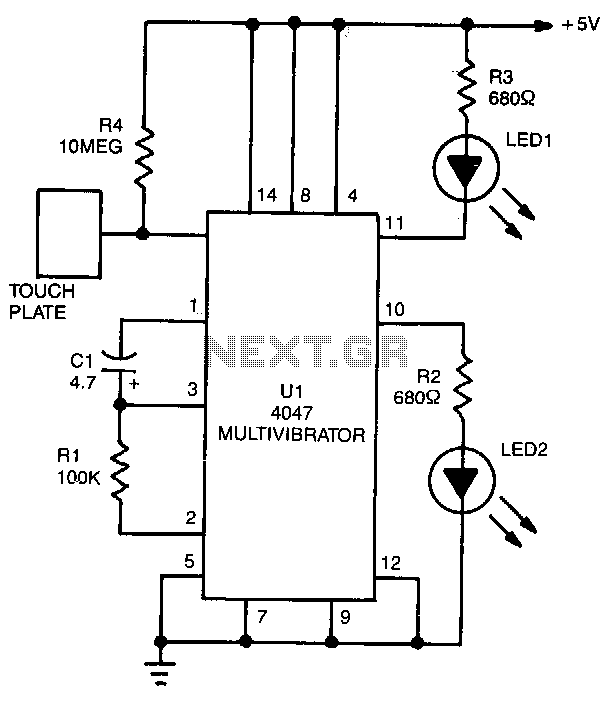
LED1 and LED2 indicators activate and stay illuminated each time the circuit is triggered. During the timing cycle, the Q output at pin 10 of U1 becomes positive when the Q output at pin 11 turns negative. The two...
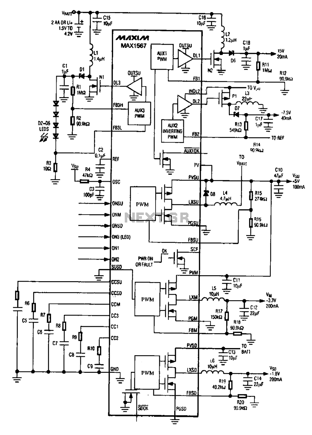
A brush 6-channel camera power supply circuit utilizing the MAX1566/1567. This circuit features a PWM generation system that is divided into six groups, with each group managing a separate channel. The circuit converts the DC voltage from the battery...
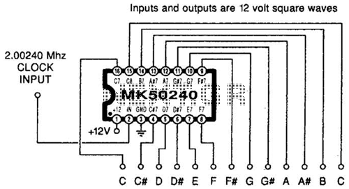
Using an MK50240, this circuit generates 12 top octave tones. The input and output lines can be separated using a binary divider IC to achieve the lower notes. Inputs and outputs are 12-volt square waves. The MK50240 is a specialized...