
LED Audio Level Meter Circuit Schematic Diagram

This audio level meter circuit is designed to visually represent audio signal levels through the illumination of LEDs, providing a clear indication of audio intensity. The use of the LM324 quad op-amp allows for efficient processing of the audio signal, enabling the circuit to handle multiple channels if more op-amps are added. Each op-amp can be configured to drive a specific LED, thus creating a multi-segment display that responds dynamically to the incoming audio levels.
The configuration of the resistors plays a critical role in determining the threshold at which each LED will activate, allowing for a graduated response to audio input levels. The 1K resistors ensure that the LEDs turn on in a staggered manner, providing a visual gradient that corresponds to the amplitude of the audio signal. Careful selection of these resistors is necessary to achieve the desired response characteristics, ensuring that the meter accurately reflects the audio levels without saturating or failing to activate under certain conditions.
The inclusion of a 50K potentiometer for sensitivity adjustment allows for customization based on the specific application and the expected range of audio input levels. This feature is particularly useful in environments where audio signals may vary significantly, enabling the user to fine-tune the responsiveness of the meter to ensure optimal performance.
In terms of input handling, the circuit is designed to accept line-level signals, making it suitable for integration with various audio equipment. The modification potential for speaker inputs expands its usability, allowing it to be adapted for different audio sources. The careful design of the input stage, including the use of a 33K resistor, helps to prevent distortion and maintain signal integrity, which is essential for accurate level representation.
Overall, this LED audio level meter circuit is a versatile tool for audio engineers and enthusiasts alike, providing a simple yet effective means of visualizing audio levels in real-time. The ability to customize and expand the circuit further enhances its applicability across a range of audio processing scenarios.This circuit uses two quad op-amps to form an eight LED audio level meter. The op-amp used in this particular circuit is the LM324. It is a popular IC and should be available from many parts stores. The 1K resistors in the circuit are essential so that the LED`s turn on at different audio levels. There is no reason why you can`t change these resis tors, although anything above 5K may cause some of the LED`s to never switch on. This circuit is easily expandable with more op-amps, and is not limited to use with the LM324. Pretty much any op-amp will work as long as you look up the pinouts and make sure everything is properly connected. The 33K resistor on the schematic is to keep the signal input to the circuit at a low level. It is unlikely you will find a 33K resistor, so the closest you can get should do. The value of this resistor may need to be changed, so it is best you breadboard this circuit before actually constructing it on PCB.
The circuit in it`s current form will accept line level inputs from sources such as the aux out on a Hi-Fi, all though could be easily modified to accept speaker inputs. The audio + is connected to the main positive rail, while the audio - is used for signal input. The 50k pot can be used to vary the sensitivity of the circuit. You are reading the Circuits of LED Audio Level Meter Circuit And this circuit permalink url it is 🔗 External reference
Related Circuits
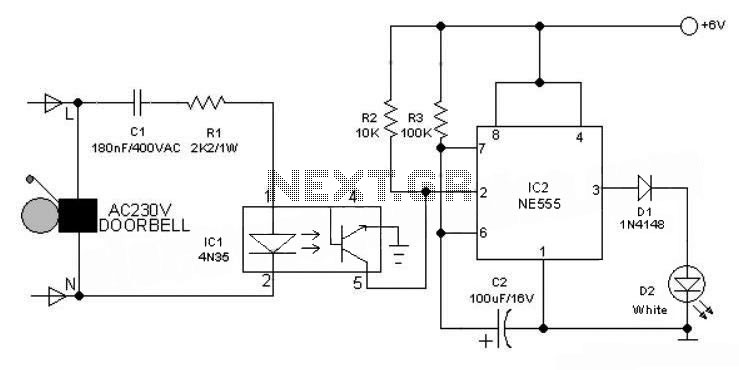
This 6V battery-operated doorbell light circuit can be connected in parallel with any existing AC 230V doorbell. When the doorbell switch is pressed, the bell sounds as usual, and the AC mains supply available across the doorbell is routed...
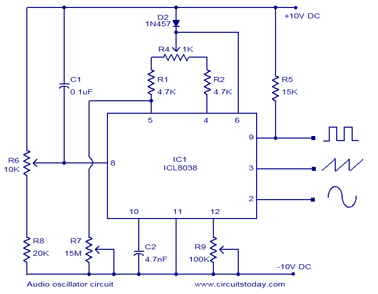
ICL8038-based audio oscillator circuit. Simultaneous sine, triangle, and square waveforms. Dual supply operation. Covers the full audio frequency range. The ICL8038 is a precision waveform generator integrated circuit that can produce sine, triangle, and square waveforms simultaneously. This versatility makes...

This is a low-cost FM antenna booster designed to enhance reception of programs from distant FM stations. The FM antenna booster circuit features a common-emitter tuned RF preamplifier utilizing the VHF/UHF transistor 2SC2570 (C2570). The schematic illustrates the configuration...
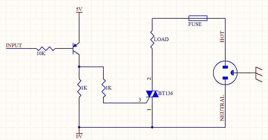
A circuit was designed to function as a light dimmer, utilizing a BT136 SCR and an MOC3022 optocoupler. However, the circuit did not operate as intended. The circuit aims to control the brightness of a light source through phase control...
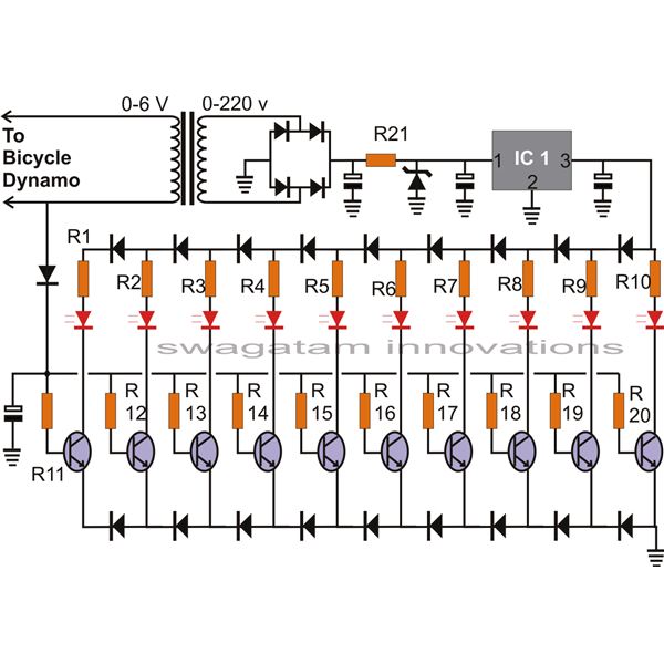
The article presents a circuit that can be used for indicating the riding speed of a bicycle. The bicycle speedometer circuit explained here utilizes standard components such as transistors and LEDs to effectively display a clear 10-step, accurately calibrated...
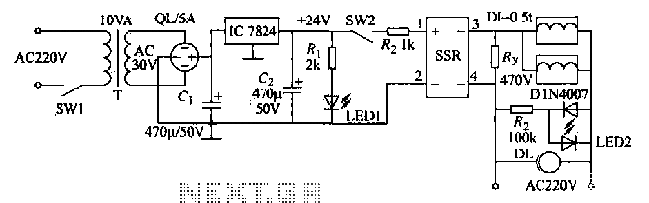
An AC solenoid-driven control circuit utilizing the SSR principle is illustrated. When switch SW1 is closed, a 220V AC transformer steps down the voltage to 30V AC through transformer T. The circuit includes a rectifier, capacitor C, and a...