
Drive Safely wth Speed Alarm

To enhance vehicle safety at high speeds, an audio alarm system can be integrated into the vehicle's dashboard. This system can be designed to monitor the vehicle's speed in real-time and provide immediate audio feedback when the speed approaches or exceeds a predetermined threshold.
The primary components of the audio alarm system include a speed sensor, a microcontroller, an audio output device (such as a buzzer or speaker), and a power supply. The speed sensor, typically a Hall effect sensor or a GPS module, measures the vehicle's speed and sends this data to the microcontroller.
The microcontroller, programmed with specific speed limits, continuously compares the incoming speed data against these limits. When the speed exceeds the set threshold, the microcontroller activates the audio output device, which emits a sound alert to notify the driver. This alert can be a continuous tone or a series of beeps, depending on design preferences.
For optimal performance, the circuit should include a power management system to ensure that the audio alarm operates reliably without draining the vehicle's battery. Additionally, a user interface with adjustable settings for speed thresholds and alarm volume can be integrated to allow customization according to driver preferences.
Overall, this audio alarm system serves as an effective safety enhancement, reducing the need for drivers to divert their attention from the road while maintaining awareness of their speed.At high speed, visually checking your speedometer to keep under maximum speed can be dangerous. It will be much safer if we put an audio alarm system to give a.. 🔗 External reference
Related Circuits

In typical push-pull driver applications, the NPN-PNP transistor pair is alternately activated and deactivated using a square-wave signal. A basic driver circuit employs an inverter between the V1 and V2 inputs to toggle the output transistors. However, mismatched turn-on...
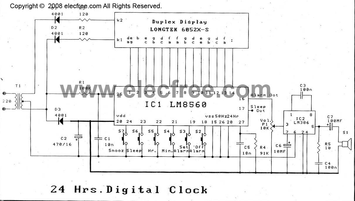
The digital time clock circuit is of great interest to electronic amateurs. The most popular clock ICs include the LM8361 and MM5387. Unfortunately, these ICs... The digital time clock circuit serves as an essential component for various electronic applications, providing...
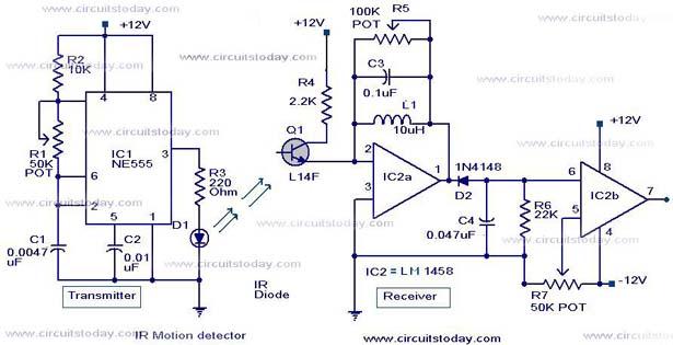
Infrared (IR) Motion Detector Circuit featuring a motion detector alarm and an infrared sensor. The circuit diagram and its operation are provided in detail. The infrared (IR) motion detector circuit is designed to detect motion within a specified range and...
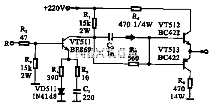
The CRT final video driver amplifier is a complementary push-pull final video driver amplifier composed of three transistors. VT511 functions as a driver amplifier, utilizing a common emitter configuration that offers high gain characteristics. The input signal from the...
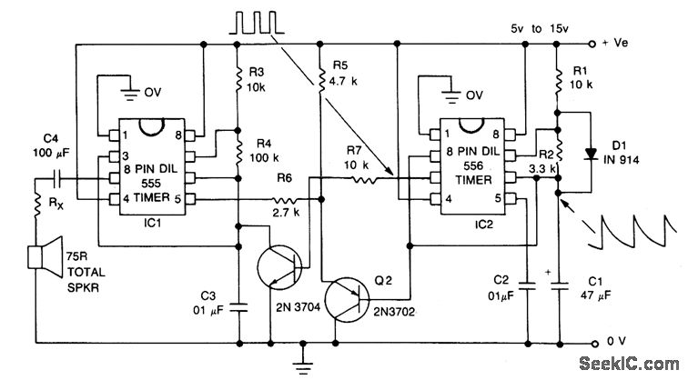
The signal begins at a low frequency, increases over approximately 1.15 seconds to a high frequency, pauses for about 0.35 seconds, and then starts to rise again from a low frequency, continuing this pattern indefinitely. The described signal exhibits a...

This alarm features both open-loop and closed-loop detection systems along with an automatic alarm shutoff mechanism. It provides a 15-second delay for exit and entrance. Additionally, the alarm activation time can be adjusted from 1 to 15 minutes. The alarm...