
Driving circuit schematic

The driving circuit serves as an essential interface between the microcontroller and the air conditioning system. It utilizes digital signals from the microcontroller to engage various components of the system effectively. The microcontroller's ports P4.0 to P4.3 and P7.1 to P7.3 are configured to transmit control signals over a distance of approximately 12 feet, ensuring that the driving circuit can be positioned away from the microcontroller while maintaining reliable communication.
The output driver chip plays a crucial role in amplifying the microcontroller's signals, allowing for the control of high-power devices such as stepper motors and relays. The stepper motor is responsible for precise positioning and control of airflow, while the relays K4, K5, and K1 manage the operational states of various components, including the indoor fan and compressor.
The fan operation is controlled to provide different speed settings, which is essential for maintaining optimal indoor climate conditions. The medium speed setting allows for balanced airflow, while the compressor control functionality enables the system to efficiently manage cooling cycles, turning on or off as required based on the environmental conditions and user settings.
In summary, this driving circuit is a sophisticated arrangement that integrates microcontroller signals with power management components to deliver efficient control of an air conditioning system, enhancing user comfort and system performance.Driving Circuit: the driving circuit shown in Figure 18-12. Driving portion is connected to the microcontroller and the air conditioning operation member of the bridge. Microco ntroller digital signal level P4. 0-P4.3 port (~ 12 feet foot) and P7. 1-P7.3 port ( ~ foot foot) to the output driver chip can be to control the stepper motor and the relay K4, K5, Kl is energized. Thus realizing the fan, the indoor fan speed, medium speed and compressor open to stop control.
Related Circuits
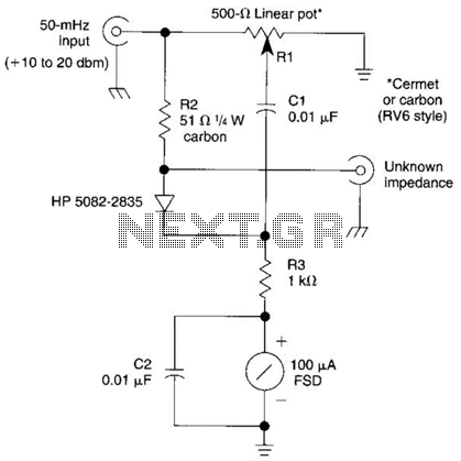
The bridge shown was used for measurements on 50-MHz amateur radio antennas. Rl is a miniature 500 linear potentiometer. The unknown impedance is compared to R2, a 51-ohm resistor. An external signal source is required. The described bridge circuit is...
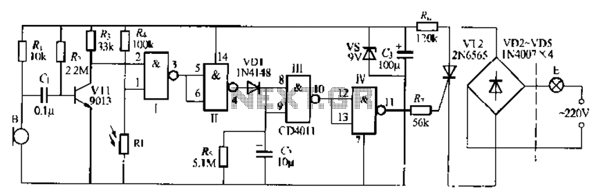
The CDI011 integrated circuit is designed for a sound and light-controlled stair delay switch circuit, which is relatively simple and effective. It utilizes a combination of NAND gates and differential input dynamics. The circuit has two input terminals; when...
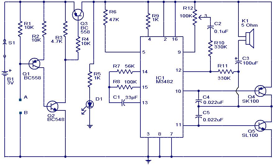
This circuit is a simple musical alarm that generates a tone when water or another conductive liquid touches the two sensor wires provided. It utilizes four transistors and a melody generator integrated circuit (IC) M3482. When water bridges the...
Here is the schematic diagram for a 20 Watt driver. I developed this circuit in 1985, and used it to build a lamp that found much use both as camping light and as emergency light during the then-frequent power...
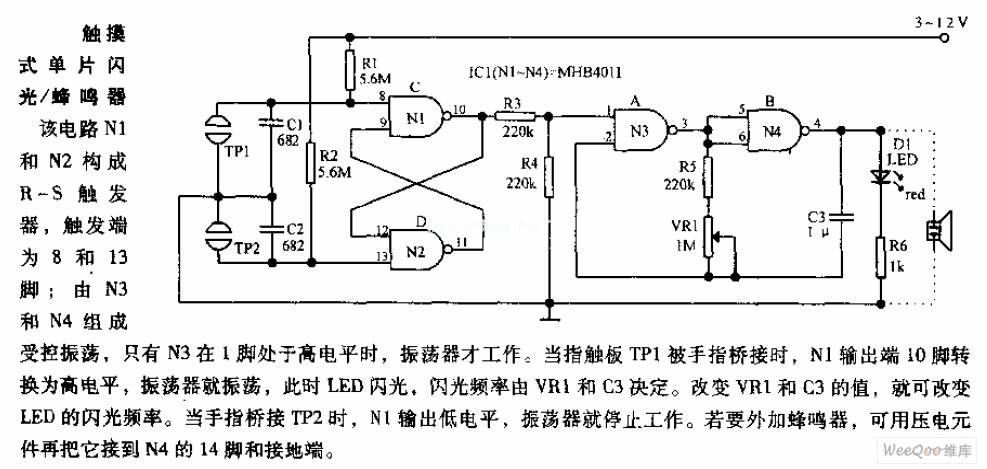
In the circuit, N1 and N2 form the RS flip-flop, with the trigger inputs located at pins 8 and 13. N3 and N4 create a controlled oscillator that operates only when pin 1 of N3 is high. When the...
The initial intention was to name the product "Chimera," but due to an existing synth company with that name, it was decided to use "Cerberus" to avoid confusion. The term "Tricephalic Filter" was deemed less appealing. Similar to its...