
drm direct mixer ef956ak5

This hybrid DRM receiver circuit integrates a single valve (EP95) and a single transistor to provide robust performance characterized by significant large-signal stability. The EP95 valve operates as a mixer, enabling the processing of DRM signals. The oscillator signal is injected into the mixer via the screen grid, which is a critical point for achieving the desired mixing process. The crystal oscillator, essential for frequency stability, is implemented using a single transistor, which contributes to the overall compactness and efficiency of the design.
The circuit is powered by a 6-V supply, making it suitable for various applications where low power consumption is essential. The receiver's design allows it to achieve an impressive signal-to-noise ratio of up to 24 dB, making it competitive with more complex integrated solutions such as the NE612 IC mixer. This performance metric is crucial for ensuring clear reception of DRM signals, especially in environments with potential interference.
The component values in the schematic are specifically tailored for the RTL2 DRM channel operating at 5990 kHz. This careful selection allows for the use of an economical 6-MHz crystal, which is a significant advantage in terms of cost-effectiveness and availability. The input circuit employs a fixed inductor, which aids in maintaining circuit stability and performance consistency.
Two trimmer capacitors are incorporated into the design to facilitate antenna matching optimization. This feature is vital for maximizing the receiver's sensitivity and overall performance, enabling it to adapt to varying antenna characteristics and environmental conditions. The operating point of the valve is controlled by the cathode resistor value, which is a critical parameter in determining the receiver's performance. Adjusting the cathode resistor can enhance the grid bias and input impedance, allowing for fine-tuning of the receiver's response. However, it is notable that satisfactory operation can still be achieved with the cathode directly grounded, providing flexibility in circuit design and implementation.This hybrid DRM receiver with a single valve and a single transistor features good large-signal stability. The EP95 (US equivalent: 6AK5) acts as a mixer, with the oscillator signal being injected via the screen grid.
The crystal oscillator is built around a single transistor. The entire circuit operates from a 6-V supply. The receiver achieves a signal-to-noise ratio of up to 24 dB for DRM signals. That means the valve can hold its own against an NE612 IC mixer. The component values shown in the schematic have been selected for the RTL2 DRM channel at 5990 kHz. That allows an inexpensive 6-MHz crystal to be used. The input circuit is built using a fixed inductor. Two trimmer capacitors allow the antenna matching to be optimized. The operating point is set by the value of the cathode resistor. The grid bias and input impedance can be increased by increasing the value of the cathode resistor. However, good results can also be achieved with the cathode connected directly to ground. 🔗 External reference
Related Circuits
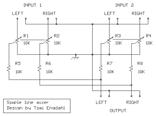
The mixer circuit described features three line inputs and three microphone inputs. The microphone inputs are designed for low impedance dynamic microphones with a range of 200 to 1000 ohms. Alternatively, an electret condenser microphone (ECM) can be used,...
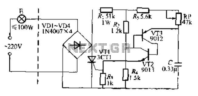
The circuit is a one-way ordinary transistor-triggered dimmer light circuit. It uses a complementary amplifier configuration with transistors VT2 and VT3 to form the thyristor trigger circuit for VT1. The circuit operates with a 220V alternating current through the...
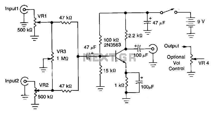
This circuit mixer features internal amplification using a 2N3563 transistor. Two input signals can be independently adjusted via VRI and VR2. The VR3 balance control allows for the attenuation of one signal while the other remains active. Additionally, the...
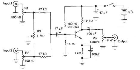
This audio mixer circuit diagram electronic project is designed using a few common electronic components. The audio mixer circuit project has two input channels. The input signal can be independently controlled using the R1 and R2 variable resistors. The...
A lot of friends ask me a circuit AUDIO MIXER, for various uses. I will begin with a circuit which you can it manufacture, as you want. This you can place in the MODULES of inputs any circuit you...
The circuit below is designed to be used with the bi-directional lamp sequencer shown above on this same page. Two additional transistors are used to increase the current from the 74HCT138 decoder to control 12 volt 25 watt lamps....