
Two channel audio mixer circuit design electronic project

The audio mixer circuit is a versatile design that allows for the blending of two audio signals, making it suitable for various applications, including live sound reinforcement and studio recording. The circuit comprises two primary input channels, each equipped with a variable resistor (R1 and R2), which serves as a volume control for their respective audio signals. This configuration enables the user to adjust the amplitude of each input independently, facilitating a balanced mix.
The R3 variable resistor acts as a crossfader, providing a smooth transition between the two audio signals. By adjusting R3, one can gradually decrease the volume of one channel while simultaneously increasing the volume of the other. This feature is particularly useful in live performance settings where seamless audio transitions are required.
The 2N3563 NPN transistor is employed as the main amplification device in the circuit. It enhances the overall gain of the mixed audio signal, ensuring that the output maintains a sufficient level for further processing or amplification. The transistor's characteristics are well-suited for audio applications, providing low distortion and a wide frequency response.
Additional passive components, such as capacitors and resistors, may be included in the circuit to filter unwanted noise and stabilize the signal. Proper grounding and layout considerations are essential to minimize interference and ensure optimal performance. Overall, this audio mixer circuit is a practical and efficient solution for combining multiple audio sources, making it an excellent project for electronics enthusiasts and professionals alike.This audio mixer circuit diagram electronic project is designed using few common electronic components. This audio mixer circuit project has two input channels. The input signal can be independently controlled using the R1 and R2 variable resistors. The R3 variable resistor offers possibility to fade out one of the signal while the other signal is fading in. The gain of the mixer is provided by the 2N3563 NPN transistor. 🔗 External reference
Related Circuits

This design outlines a phone bug circuit. The wireless telephone line spy circuit is capable of transmitting phone conversations to a nearby FM radio. The circuit must be connected to a standard phone line. In the circuit, the first...
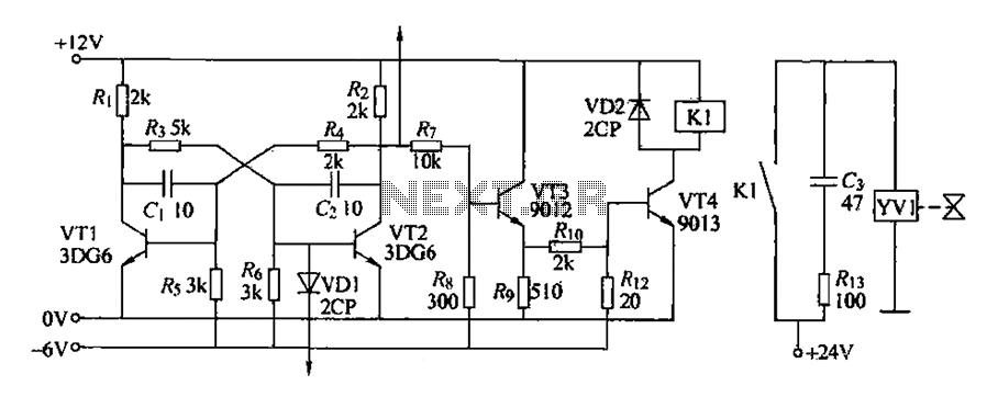
The circuit for detecting bad book binding is not illustrated. The solenoid valve is used to control the head of the YV1 mechanism for handling bad books. Under constant conditions, there is no positive signal indicating a bad book....
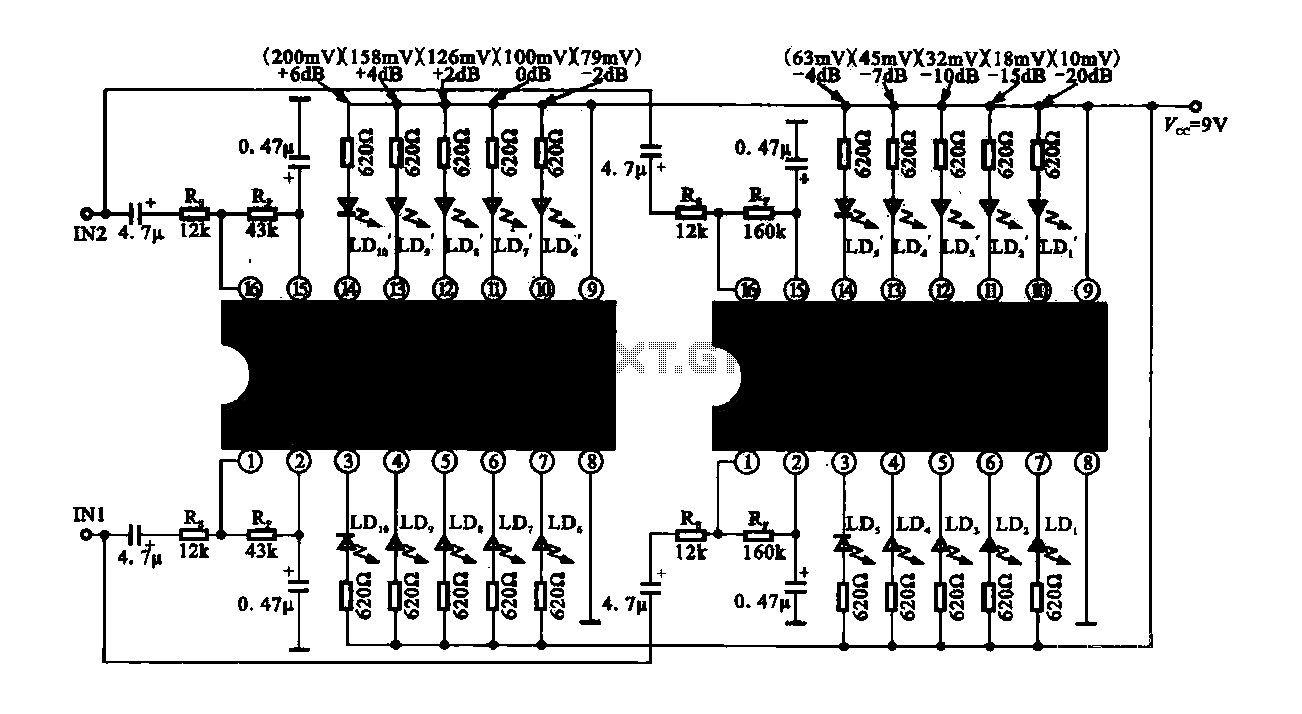
The circuit consists of dual drive integrated circuits (ICs) utilized in a 10 LED level meter configuration. The schematic features two TLM8101 driver ICs, which can be employed as alternatives. The 10 LED level meter circuit is designed to provide...

Audio Graphic Equalizer. Audio graphic equalizers are widely used as commercial products in high-fidelity systems, car audio, and stage applications; however, circuits for these devices are seldom published. Audio graphic equalizers are essential tools in audio processing, allowing users to...
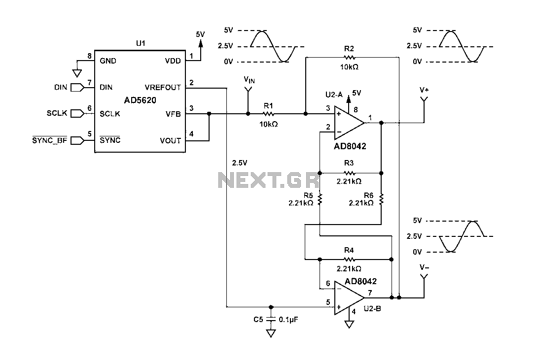
Figure 1 illustrates a circuit that utilizes a single +V power supply and a voltage output Digital-to-Analog Converter (DAC) known as the AD5620. The DAC is controlled via an SPI port, with its output ranging from 0 V to...
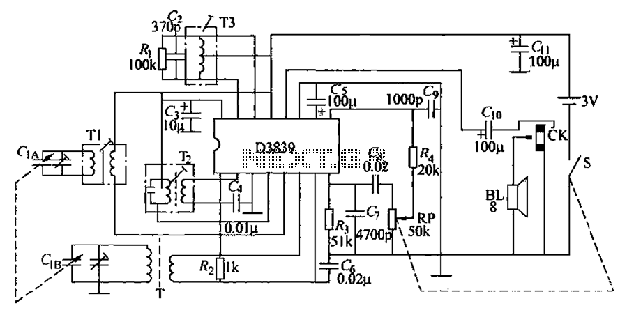
The circuit operates by utilizing a high-frequency section of the antenna to receive AM radio signals, amplifying radio-frequency signals at a selected vibration level of 465 kHz. The intermediate frequency (IF) signal is processed through an IF amplifier, followed...