
Ni-cad charger with current and voltage limiting

The described circuit operates as a battery charging indicator and protection mechanism. The main components include a light bulb (LI), an LED, a diode (D1), and a Zener diode (Z1). The light bulb serves as a visual indication of the charging state of the battery. When the battery voltage is low, the circuit allows for a higher current draw, illuminating the light bulb brightly to signal that charging is in progress. The LED remains off during this state to prevent confusion about the charging status.
As the battery approaches full charge, the circuit transitions to a lower current state. In this condition, the LED lights up brightly, indicating that the battery is nearly charged, while the light bulb dims due to reduced current flow. This dual indication helps users easily monitor the charging process and the battery's health.
The diode (D1) is critical for ensuring that the current does not exceed 1 A, protecting the circuit from potential damage due to excessive current. The Zener diode (Z1) plays a vital role in voltage regulation; it is selected based on the full-charge voltage of the battery, minus a 1 V margin to allow for safe operation without overcharging.
Once fully charged, the circuit enters a float charge mode, where it maintains a small current, approximately equal to the battery capacity divided by 100 mA. This float charging is essential for maintaining the battery's charge without overcharging, thereby extending its life and ensuring reliable performance. The design of this circuit provides a straightforward and effective solution for battery management, combining visual indicators with protective components to enhance usability and safety.Lamp LI will glow brightly and the LED will be out when the battery is low and being charged, but the LED will be bright and the light bulb dim when the battery is almost ready. Ll should be a light bulb rated for the current you want (usually the battery capacity divided by 10).
Diode D1 should be at least 1 A, and Z1 is a 1W zener diode with a voltage determined by the full-charge battery voltage minus 1 V After the battery is fully charged, the circuit will float it at about battery capacity divided by 100 mA.
Related Circuits
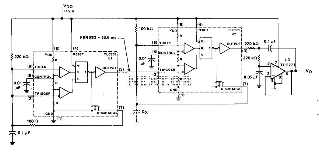
The timer U1 operates as a free-running oscillator at 60 Hz, providing trigger pulses to timer U2, which functions in monostable mode. Resistor R1 is fixed, while capacitor Cx is the capacitor being measured. The output of U2 is...
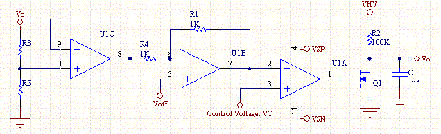
This circuit enables a smaller control voltage to inversely and linearly control a larger output voltage (Vo). Additionally, the supply voltage (Vsp) for the operational amplifiers can be lower than the output voltage, allowing the circuit to theoretically control...
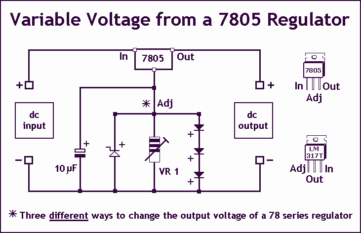
Controlling the output voltage from a regulator can be made variable in three ways: 1. Using a fixed reference zener diode to increase the output by the value of the zener 2. A variable resistor for variable output, note...
Power line fluctuations and cut-offs can damage electrical appliances connected to the line, particularly domestic appliances like refrigerators and air conditioners. When a refrigerator operates on low voltage, excessive current flows through the motor, leading to overheating and potential...
Many applications require highly efficient negative-voltage post regulators with low dropout voltage in switch-mode supplies. A method to achieve effective negative-voltage regulation is by utilizing a low-dropout positive-voltage regulator that operates from a well-isolated secondary winding of the switch-mode...
An alternative approach involves obtaining a motor's counter electromotive force from the motor end of the related signal after it has been amplified and averaged across three pins. The drive output A functions as a single-ended output, which controls...